Teccor® brand Protection Thyristors
Axial Leaded
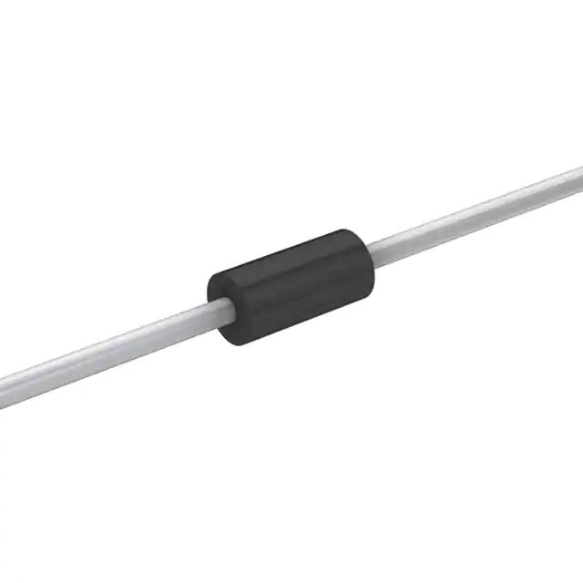
DO-41 Series SIDACtor® Device
Description
This DO-41 plastic package provides a through-hole version
of the SIDACtor® devices. This axial leaded device is ideal for
Customer Premises Equipment (CPE) such as telephones,
answering machines, modems, and fax interfaces. The DO-41
package series can also be used for overvoltage protection
for applications such as T1/E1/J1 trunk cards when the
appropriate overcurrent protection is included.
Features
•R
� oHS compliant
• �Bidirectional transient voltage protection
• �Axial lead through-hole component
• �Teccor brand SIDACtor technology
Agency Approvals
Agency
Agency File Number
E133083
Protection solution to meet
•Y
� D/T 950
• �YD/T 993
• �YD/T 1082
•G
� R 1089 Intra-building
• I�EC 61000-4-5
• �ITU K.20/21 Basic Level
• �TIA-968-A Type B Surges
Electrical Characteristics
VDRM
@lDRM=5µA
VS
@100V/µs
Volts
Volts
IH
IS
IT
VT
@IT=1 amp
Capacitance
@1MHz, 2V bias
Amps
Volts
pF
Part Number
Marking
Min
Max
Min
Max
Max
Max
Typical
P1100THLRP
P11H
90
130
150
800
1.0
5
60
P1300THLRP
P13H
120
160
150
800
1.0
5
40
P1500THLRP
P15H
140
180
150
800
1.0
5
40
mAmps mAmps
P1800THLRP
P18H
170
220
150
800
1.0
5
40
P2300THLRP
P23H
190
260
150
800
1.0
5
30
P2600THLRP
P26H
220
300
150
800
1.0
5
30
P3100THLRP
P31H
275
350
150
800
1.0
5
30
P3500THLRP
P35H
320
400
150
800
1.0
5
30
• �All measurements are made at an ambient temperature of 25°C.
• �Listed SIDACtor devices are bidirectional. All electrical parameters and surge ratings
apply to forward and reverse polarities.
DO-41 Series
Specifications are subject to change without notice.
�
Telecom Design Guide
www.littelfuse.com
©2006 Littelfuse
�Teccor® brand Protection Thyristors
Axial Leaded
Surge Ratings
IPP
Series
5x320 µs
10x1000 µs
Amps
Amps
Min
Min
25
35
H
• �IPP applies to -40°C through +85°C temperature range.
• I�PP is a repetitive surge rating and is guaranteed for the life of the product.
V-I Characteristics
tr x td Pulse Waveform
IT
IS
IH
IDRM
-V
+V
VT
VDRM
VS
IPP – Peak Pulse Current – %IPP
+I
100
50
0
IH (TC = 25 ˚C)
IH
6
25 ˚C
4
2
0
-4
-6
-8
-40 -20
0
Junction Temperature (TJ) – ˚C
Specifications are subject to change without notice.
td
t – Time (µs)
2.0
1.8
1.6
1.4
25 ˚C
1.2
1.0
0.8
0.6
0.4
-40 -20 0
20 40 60 80 100 120 140 160
Case Temperature (TC) – ˚C
20 40 60 80 100 120 140 160
DO-41 Series
tr
Normalized DC Holding Current Versus Case Temperature
Ratio of
Percent of VS Change – %
8
Half Value
0
14
12
10
tr = rise time to peak value
td = decay time to half value
Waveform = tr x td
-I
Normalized VS Change Versus Junction Temperature
Peak
Value
�
Telecom Design Guide
www.littelfuse.com
©2006 Littelfuse
�Teccor® brand Protection Thyristors
Axial Leaded
Soldering Parameters
Pb – Free assembly
Reflow Condition
Pre Heat
- Temperature Min (Ts(min))
150°C
- Temperature Max (Ts(max))
190°C
- Time (min to max) (ts)
50 – 150 seconds
Average ramp up rate (Liquidus Temp
(TL) to peak)
5°C/second max
TS(max) to TL - Ramp-up Rate
5°C/second max
Reflow
- Temperature (TL) (Liquidus)
220°C
- Time (min to max) (ts)
>60 –
很抱歉,暂时无法提供与“P3100THLRP”相匹配的价格&库存,您可以联系我们找货
免费人工找货