SA10CA

SA10CA

  • 厂商:

    HAMLIN

  • 封装:

    DO15

  • 描述:

    SA系列专为保护敏感电子设备免受雷击及其他瞬态电压事件引起的电压瞬变影响而设计。

  • 详情介绍
  • 数据手册
  • 价格&库存
SA10CA 数据手册
TVS Diodes Axial Leaded – 500W > SA series SA Series RoHS Pb e3 Description Bi-directional The SA Series is designed specifically to protect sensitive electronic equipment from voltage transients induced by lightning and other transient voltage events. Features Uni-directional Agency Approvals Agency Agency File Number E230531 Maximum Ratings and Thermal Characteristics (TA=25OC unless otherwise noted) Parameter Symbol Value Unit Peak Pulse Power Dissipation by 10/1000μs Test Waveform (Fig.2)(Note 1) PPPM 500 W Steady State Power Dissipation on Infinite Heat Sink at TL=75ºC PD 3.0 W Peak Forward Surge Current, 8.3ms Single Half Sine Wave Unidirectional Only (Note 2) IFSM 70 A Maximum Instantaneous Forward Voltage at 35A for Unidirectional Only VF 3.5 V Operating Junction and Storage Temperature Range TJ , TSTG -65 to 175 °C Typical Thermal Resistance Junction to Lead RθJL 20 °C/W Typical Thermal Resistance Junction to Ambient RθJA 75 °C/W Notes: 1. Non-repetitive current pulse , per Fig. 4 and derated above TJ (initial) =25OC per Fig. 3. 2. Measured on 8.3ms single half sine wave or equivalent square wave, duty cycle=4 per minute maximum. • 500W peak pulse capability at 10/1000μs waveform, repetition rate (duty cycles):0.01% • VBR @ TJ= VBR@25°C x (1+αT x (TJ - 25)) (αT:Temperature Coefficient, typical value is 0.1%) • Glass passivated chip junction in DO-15 Package • Fast response time: typically less than 1.0ps from 0 Volts to BV min • Excellent clamping capability • Typical failure mode is short from over-specified voltage or current • Whisker test is conducted based on JEDEC JESD201A per its table 4a and 4c • IEC-61000-4-2 ESD 30kV(Air), 30kV (Contact) • ESD protection of data lines in accordance with IEC 61000-4-2 • EFT protection of data lines in accordance with IEC 61000-4-4 • Low incremental surge resistance • Typical IR less than 1μA when VBR max>13V • High temperature to reflow soldering guaranteed: 260°C/40sec / 0.375”,(9.5mm) lead length, 5 lbs., (2.3kg) tension • Plastic package is flammability rated V-0 per Underwriters Laboratories • Matte tin lead–free plated • Halogen free and RoHS compliant • Pb-free E3 means 2nd level interconnect is Pbfree and the terminal finish material is tin(Sn) (IPC/ JEDEC J-STD-609A.01) Applications TVS devices are ideal for the protection of I/O interfaces, VCC bus and other vulnerable circuits used in telecom, computer, industrial and consumer electronic applications. Functional Diagram Additional Infomarion Datasheet Bi-directional Cathode Resources Samples Anode Uni-directional © 2020 Littelfuse, Inc. Specifications are subject to change without notice. Revised: BA.08/31/20 TVS Diodes Axial Leaded – 500W > SA series Electrical Characteristics (T =25°C unless otherwise noted) A Part Number (Uni) SA5.0A SA6.0A SA6.5A SA7.0A SA7.5A SA8.0A SA8.5A SA9.0A SA10A SA11A SA12A SA13A SA14A SA15A SA16A SA17A SA18A SA20A SA22A SA24A SA26A SA28A SA30A SA33A SA36A SA40A SA43A SA45A SA48A SA51A SA54A SA58A SA60A SA64A SA70A SA75A SA78A SA85A SA90A SA100A SA110A SA120A SA130A SA150A SA160A SA170A SA180A Part Number (Bi) SA5.0CA SA6.0CA SA6.5CA SA7.0CA SA7.5CA SA8.0CA SA8.5CA SA9.0CA SA10CA SA11CA SA12CA SA13CA SA14CA SA15CA SA16CA SA17CA SA18CA SA20CA SA22CA SA24CA SA26CA SA28CA SA30CA SA33CA SA36CA SA40CA SA43CA SA45CA SA48CA SA51CA SA54CA SA58CA SA60CA SA64CA SA70CA SA75CA SA78CA SA85CA SA90CA SA100CA SA110CA SA120CA SA130CA SA150CA SA160CA SA170CA SA180CA Reverse Stand off Voltage VR (V) 5.0 6.0 6.5 7.0 7.5 8.0 8.5 9.0 10.0 11.0 12.0 13.0 14.0 15.0 16.0 17.0 18.0 20.0 22.0 24.0 26.0 28.0 30.0 33.0 36.0 40.0 43.0 45.0 48.0 51.0 54.0 58.0 60.0 64.0 70.0 75.0 78.0 85.0 90.0 100.0 110.0 120.0 130.0 150.0 160.0 170.0 180.0 Breakdown Voltage VBR (Volts) @ IT Min. 6.40 6.67 7.22 7.78 8.33 8.89 9.44 10.00 11.10 12.20 13.30 14.40 15.60 16.70 17.80 18.90 20.00 22.20 24.40 26.70 28.90 31.10 33.30 36.70 40.00 44.40 47.80 50.00 53.30 56.70 60.00 64.40 66.70 71.10 77.80 83.30 86.70 94.40 100.00 111.00 122.00 133.00 144.00 167.00 178.00 189.00 200.00 Max. 7.00 7.37 7.98 8.60 9.21 9.83 10.40 11.10 12.30 13.50 14.70 15.90 17.20 18.50 19.70 20.90 22.10 24.50 26.90 29.50 31.90 34.40 36.80 40.60 44.20 49.10 52.80 55.30 58.90 62.70 66.30 71.20 73.70 78.60 86.00 92.10 95.80 104.00 111.00 123.00 135.00 147.00 159.00 185.00 197.00 209.00 221.00 Test Current IT (mA) 10 10 10 10 1 1 1 1 1 1 1 1 1 1 1 1 1 1 1 1 1 1 1 1 1 1 1 1 1 1 1 1 1 1 1 1 1 1 1 1 1 1 1 1 1 1 1 Maximum Clamping Voltage VC@ IPP (V) 9.2 10.3 11.2 12.0 12.9 13.6 14.4 15.4 17.0 18.2 19.9 21.5 23.2 24.4 26.0 27.6 29.2 32.4 35.5 38.9 42.1 45.4 48.4 53.3 58.1 64.5 69.4 72.7 77.4 82.4 87.1 93.6 96.8 103.0 113.0 121.0 126.0 137.0 146.0 162.0 177.0 193.0 209.0 243.0 259.0 275.0 289.0 Maximum Peak Pulse Current Ipp (A) Maximum Reverse Leakage IR @ VR (µA) Agency Approval 600 600 400 150 50 25 10 5 3 1 1 1 1 1 1 1 1 1 1 1 1 1 1 1 1 1 1 1 1 1 1 1 1 1 1 1 1 1 1 1 1 1 1 1 1 1 1 X X X X X X X X X X X X X X X X X X X X X X X X X X X X X X X X X X X X X X X X X X X X X X X 55.4 49.5 45.5 42.5 39.5 37.5 35.4 33.1 30.0 28.0 25.6 23.7 22.0 20.9 19.6 18.5 17.5 15.7 14.4 13.1 12.1 11.2 10.5 9.6 8.8 7.9 7.3 7.0 6.6 6.2 5.9 5.4 5.3 5.0 4.5 4.2 4.0 3.7 3.5 3.1 2.9 2.6 2.4 2.1 2.0 1.9 1.7 For bidirectional type having VR of 10 volts and less, the IR limit is double. For parts without A , the VBR is ± 10% and Vc is 5% higher than with A parts, the parts without A are currently available, but not recommended for new designs. The parts with A are preferred. © 2020 Littelfuse, Inc. Specifications are subject to change without notice. Revised: BA.08/31/20 TVS Diodes Axial Leaded – 500W > SA series I-V Curve Characteristics Uni-directional Bi-directional Ipp Vc VBR VR V IR VF IT IT IR Vc VBR VR IR IT Ipp PPPM VR VBR VC IR VF VR VBR Vc V Ipp Peak Pulse Power Dissipation -- Max power dissipation Stand-off Voltage -- Maximum voltage that can be applied to the TVS without operation Breakdown Voltage -- Maximum voltage that flows though the TVS at a specified test current (IT) Clamping Voltage -- Peak voltage measured across the TVS at a specified Ippm (peak impulse current) Reverse Leakage Current -- Current measured at VR Forward Voltage Drop for Uni-directional Ratings and Characteristic Curves (T =25°C unless otherwise noted) A Figure 1 - TVS Transients Clamping Waveform Figure 2 - Peak Pulse Power Rating Voltage Transients 100 PPPM - Peak Pulse Power(KW) TJ initial = Tamb Voltage or Current Voltage Across TVS Current Through TVS 10 1 0.1 0.001 0.01 0.1 1 10 Td - Pulse Width(ms) Time © 2020 Littelfuse, Inc. Specifications are subject to change without notice. Revised: BA.08/31/20 TVS Diodes Axial Leaded – 500W > SA series Ratings and Characteristic Curves (T =25°C unless otherwise noted) (Continued) A Figure 3 - Peak Pulse Power Derating Curve Figure 4 - Pulse Waveform 75 50 25 0 tr=10µsec IPPM- Peak Pulse Current, % IRSM Peak Pulse Power (PPP) or Current (IPP) Derating in Percentage % 150 100 0 25 50 75 100 125 150 175 Half Value IPPM IPPM ( ) 2 50 200 0 td 1.0 0 2.0 3.0 4.0 Figure 6 - Typical Transient Thermal Impedance 100 Transient Thermal Impedance ( °C/W) 10000 Bi-directional V=0V Uni-directional V=0V 1000 Uni-directional @ VR Cj (pF) 10/1000µsec. Waveform as defined by R.E.A t-Time (ms) Figure 5 - Typical Junction Capacitance 100 Bi-directional @ VR 1 1.0 Peak Value IPPM 100 TJ - Initial Junction Temperature (ºC) 10 TJ=25°C Pulse Width(td) is defined as the point where the peak current decays to 50% of IPPM Tj=25C f=1.0MHz Vsig=50mVp-p 10.0 100.0 10 1 0.1 1000.0 0.01 0.1 VBR - Reverse Breakdown Voltage (V) 1 10 100 1000 TP - Pulse Duration (s) Figure 7 - Maximum Non-Repetitive Forward Surge Current Uni-Directional Only Figure 8 - Peak Forward Voltage Drop vs Peak Forward Current (Typical Values) 100.0 100 I F - Peak Forward Current(A) IFSM - Peak Forward Surve Current(A) 120 80 60 40 10.0 1.0 20 0 1 10 Number of Cycles at 60 Hz 100 0.1 0.0 1.0 2.0 3.0 4.0 5.0 VF - Peak Forward Voltage(V) © 2020 Littelfuse, Inc. Specifications are subject to change without notice. Revised: BA.08/31/20 TVS Diodes Axial Leaded – 500W > SA series Soldering Parameters Lead–free assembly Pre Heat - Temperature Min (Ts(min)) 150°C - Temperature Max (Ts(max)) 200°C - Time (min to max) (ts) 60 – 180 secs Average ramp up rate (Liquidus Temp (TA) to peak Reflow Ramp-up TL 3°C/second max 3°C/second max TS(max) to TA - Ramp-up Rate - Temperature (TA) (Liquidus) 217°C - Time (min to max) (ts) 60 – 150 seconds Peak Temperature (TP) 260+0/-5 °C Time within 5°C of actual peak Temperature (tp) 20 – 40 seconds Ramp-down Rate 6°C/second max Time 25°C to peak Temperature (TP) 8 minutes Max. Do not exceed 260°C Case Polarity Terminal tL Critical Zone TL to TP Ts(max) Ramp-down Ts(min) ts Preheat 25˚C t 25˚C to Peak Time (t) Flow/Wave Soldering (Solder Dipping) Peak Temperature : 265OC Dipping Time : 10 seconds Soldering : 1 time Environmental Specifications Physical Specifications Weight tp TP Temperature (T) Reflow Condition 0.015oz., 0.4g JEDEC DO-204AC (DO-15) molded plastic body over passivated junction. Color band denotes the cathode except Bipolar. Matte Tin axial leads, solderable per JESD22-B102. High Temp. Storage JESD22-A103 HTRB JESD22-A108 Temperature Cycling JESD22-A104 H3TRB JESD22-A101 RSH JESD22-B106 Dimensions D Dimensions Cathode Band (for uni-directional products only) C A B Inches Millimeters Min Max Min A 1.000 - 25.40 Max - B 0.230 0.300 5.80 7.60 C 0.028 0.034 0.71 0.86 D 0.104 0.140 2.60 3.60 A DO-204AC (DO-15) © 2020 Littelfuse, Inc. Specifications are subject to change without notice. Revised: BA.08/31/20 TVS Diodes Axial Leaded – 500W > SA series Part Numbering System Part Marking System SA xxx XX X Cathode Band Option Code: Blank Reel Tape -B Bulk Packaging F (for uni-directional products only) YYWW Littelfuse Logo Type Code: A Uni-Directional (5% VBR Voltage Tolerance) CA Bi-Directional (5% VBR Voltage Tolerance) Trace Code Marking YY:Year Code WW: Week Code SAXXX VBR Voltage Code: (Refer to the Electrical Characteristics table) Product Type Series Code: Packaging SAxxxXX Component Package DO-204AC SAxxxXX-B DO-204AC Part Number 4000 Packaging Option Tape & Reel 1000 Bulk Quantity Packaging Specification EIA STD RS-296 Littelfuse Spec. Tape and Reel Specification Off Center either side 0.028(0.7) 2.56 (65.0) 0.236 (6.0) 0.047 (1.2) 0.197+/-0.020 (5.0+/- 0.5) 13.0 (330.2) 2.063+0.079/-0.039 (53.0+2.0/-1.0) Dimensions are in inches/mm 3.0 (76.2) 0.68 (17.27) 2.75 (69.85) Recess Depth Max. 0.75 (19.05) Direction of Feed Disclaimer Notice - Information furnished is believed to be accurate and reliable. However, users should independently evaluate the suitability of and test each product selected for their own applications. Littelfuse products are not designed for, and may not be used in, all applications. Read complete Disclaimer Notice at www.littelfuse.com/disclaimer-electronics. © 2020 Littelfuse, Inc. Specifications are subject to change without notice. Revised: BA.08/31/20
SA10CA
物料型号:SA系列,包括双向和单向的TVS二极管。

器件简介:SA系列是专为保护敏感电子设备免受雷电和其他瞬态电压事件引起的电压瞬变而设计的。

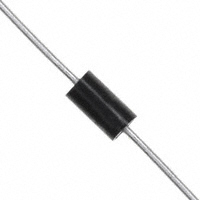
引脚分配:文档中没有明确指出引脚分配,但通常在双向TVS二极管中,带有色环的一端是阴极。

参数特性:包括最大脉冲功率耗散、稳态功率耗散、峰值正向浪涌电流、最大瞬态正向电压、工作结和存储温度范围、典型热阻等。

功能详解:SA系列具有500W的峰值脉冲能力、快速响应时间(小于1.0ps)、优秀的钳位能力、低增量浪涌电阻等。

应用信息:适用于电信、计算机、工业和消费电子应用中的I/O接口、VCC总线和其他易受攻击电路的保护。

封装信息:采用JEDEC DO-204AC(DO-15)塑封体,带有钝锡轴向引线,可按照JESD22-B102进行焊接。
SA10CA 价格&库存

很抱歉,暂时无法提供与“SA10CA”相匹配的价格&库存,您可以联系我们找货

免费人工找货
SA10CA
    •  国内价格
    • 1+2.77240

    库存:78

    SA10CA

      库存:0