SIDACtor ® Protection Thyristors
Teccor® brand SIDACtor® DSL Protection Devices
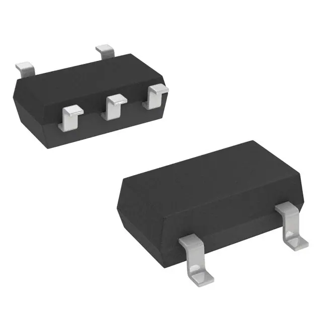
SDP Series - SOT23-5
RoHS
Pb e3
Description
This new SIDACtor series thyristors are targeted for the
tertiary or line driver side protection position for VDSL2+,
ADSL2 applications and general I/O protection functions.
This new low capacitance over voltage protection does not
require a bias voltage and is sufficiently robust for the chipside position behind the coupling transformer.
This SOT23-5 solution, with its flow-through design,
minimizes PCB trace layout routing, while its four different
stand-off voltage values offer compatibility with a variety of
line drivers. Its low capacitance makes it compatible with
ADSL2 and VDSL2, and the 30MHz bandplan of VDSL2+.
Agency Approvals
Features & Benefits
Agency
Agency File Number
E133083
Schematic Symbol
• �Lower overshooting
protection than clamping
• �Starts to switch in
nanoseconds
• �SOT23-5 surface mount
package
• RoHS compliant and
Halogen-Free
• �Low insertion loss
• �Pb-free E3 means 2nd level
interconnect is Pb-free and
the terminal finish material
is tin(Sn) (IPC/JEDEC
J-STD-609A.01)
• Low capacitance
(Tip) 1
• �Bidirectional transient
voltage protection
5 (Tip)
• �Robust surge rating
NC
Applicable Global Standards
2
(Ring) 3
4 (Ring)
• YD/T 950
• �IEC 61000-4-5 2nd edition
• YD/T 993
• ��ITU K.20/21/45 Basic Level
• �YD/T 1082
• �ITU K.20/21/45 Enhanced
Level
• �GR 1089 Inter-building
• GR 1089 Intra-building
Additional Information
Datasheet
• �TIA-968-B
• IEC 61000-4-2
Resources
• �TIA-968-A
Samples
Electrical Characteristics
VDRM@IDRM=5µA
VS@250V/µs
IH
IS
VT@IT=1.0
Amps
V min
V max
mA typ
mA max
V max
pF typ
pF max
8
15
30
500
4.0
8.0
9.0
P12G
12
20
30
500
4.0
7.8
9.0
P18G
P24G
18
24
25
35
30
30
500
500
4.0
4.0
7.3
5.7
8.3
6.5
Part Number
Marking
SDP0080T023G5RP
P8G
SDP0120T023G5RP
SDP0180T023G5RP
SDP0240T023G5RP
Notes:
- All measurement are made at an ambient temperature of 25°C.
- Ipp applies to -40°C through +85°C temperature range.
- Ipp is repetitive surge rating and is guaranteed for the life of the product.
- SIDACtor components are bidirectional. All electrical parameters and surge rating apply to
forward and reverse polarities.
© 2018 Littelfuse, Inc.
Specifications are subject to change without notice.
Revised: 05/02/18
Co@f=1MHz,2V
�SIDACtor ® Protection Thyristors
Teccor® brand SIDACtor® DSL Protection Devices
Maximum Ratings
Parameter Name
Symbol
Test Conditions
8/20
1.2/502
1
Lightning surge waveforms
Ipp
5/3101
10/7002
Value
min
Units
SDP0080T023G5RP
50
SDP0120T023G5RP
70
SDP0180T023G5RP
70
SDP0240T023G5RP
70
min
A
20
min
max
Operating Free Temperature Range
TA
-40
+85
°C
Junction temperature
TJ
-40
+150
°C
Storage temperature
TSTG
-40
+150
°C
Notes:
1. Voltage waveform in µs
2.Current waveform in µs
- The device also complies with IEC 61000-4-2 ESD ±15kV (air discharge), ±8 kV(contact discharge) and IEC 61000-4-4 EFT 40A(5/50nS) in equipment level ESD test when used behind the
xDSL transformer.
- The component must initially be in thermal equilibrium with -40°C < TJ < +150°C
- The lightning surge may be repeated after the device returns to its initial conditions.
Mechanical dimensions, recommended layout dimensions
The epoxy meets UL 94V-0 ratings.
A
0.037(0.95)
D
B
Dimension
A
A1
A2
B
C
D
E
F
G
Inches
Millimeters
Min
Max
Min
Max
0.035
0
0.035
0.014
0.004
0.11
0.059
0.102
0.004
0.057
0.004
0.051
0.020
0.008
0.118
0.069
0.118
0.024
0.90
0
0.90
0.35
0.09
2.80
1.50
2.6
0.10
1.45
0.10
1.30
0.50
0.20
3.00
1.75
3.00
0.60
E
A2
A1
C
F
G
0.037(0.95)
Dimension are in inches
(and millimeters).
0.024(0.60)
0.047(1.2)
0.138(3.5)
© 2018 Littelfuse, Inc.
Specifications are subject to change without notice.
Revised: 05/02/18
�SIDACtor ® Protection Thyristors
Teccor® brand SIDACtor® DSL Protection Devices
Thermal Considerations
Package
Symbol
Parameter
Value
Unit
TJ
Operating Junction Temperature Range
-40 to +150
°C
TSTG
Storage Temperature Range
-40 to +150
°C
R0JA
Thermal Resistance: Junction to Ambient
120
°C/W
5
4
1
2
3
Holding Current vs. Case Temperature
VS vs. Junction Temperature
14
Percent of VS Change – %
IH (TC = 25ºC)
1.8
1.6
1.4
25°C
1.2
1.0
Ratio of
IH
2.0
0.8
0.6
0.4
-40
-20
0
20
40
60
80
100 120 140
160
12
10
8
6
25 °C
4
2
0
-4
-6
-8
-40 -20
Case Temperature (TC) - ºC
0
20 40 60 80 100 120 140 160
Junction Temperature (TJ) – °C
Capacitance vs. Bias Voltage
V-I Characteristics
+I
9
Capacitance (pF)
8
IT
7
IS
IH
6
5
SDP-08
-V
4
IDRM
+V
SDP-012
3
VT
SDP-018
2
VS
SDP-024
1
0
0
2
4
6
8
10
12
14
16
Off-State Voltage (V)
© 2018 Littelfuse, Inc.
Specifications are subject to change without notice.
Revised: 05/02/18
18
20
VDRM
22
24
-I
�SIDACtor ® Protection Thyristors
Teccor® brand SIDACtor® DSL Protection Devices
SDP-xxx Application example
and the SDP3500Q38CB overvoltage protector. GDTs may
also be used on the line side of the coupling transformer. The
flow-through design of the SOT23-5 package is illustrated
below. If the inter winding capacitance of the transformer is
allowing some common mode events to get coupled across,
then the SDP-xxx0T023 can be placed in a three chip mode,
as shown below for additional chip-side protection.
The following schematics show alternate protection solutions
for a typical DSL interface that connects to outside wiring.
This surface mount SOT23-5 chip-side solution provides a
minimum footprint solution appropriate for high density card
designs. The SDP-xxx0T023 will protect the interface from
lightning induced surges on the chip-side of the coupling
transformer. This tertiary protector may be preceded by lineside protection such as the TeleLink over-current protector
DSL driver chipset
Tip
Ring
SDP-018
DSL driver chipset
Tip
Ring
(3)SDP-018
1
NC
5
PCBTrace
2
3
4
PCBTrace
© 2018 Littelfuse, Inc.
Specifications are subject to change without notice.
Revised: 05/02/18
�SIDACtor ® Protection Thyristors
Teccor® brand SIDACtor® DSL Protection Devices
Soldering Parameters
- Temperature Min (Ts(min))
Pre Heat
- Temperature Max (Ts(max))
- Time (Min to Max) (ts)
Pb-Free assembly
(see Fig. 1)
+150°C
+200°C
60-180 secs.
Average ramp up rate (Liquidus Temp (TL)
to peak)
3°C/sec. Max.
TS(max) to TL - Ramp-up Rate
3°C/sec. Max.
Reflow
- Temperature (TL) (Liquidus)
+217°C
- Temperature (tL)
60-150 secs.
Peak Temp (TP)
+260(+0/-5)°C
Time within 5°C of actual Peak Temp (tp)
30 secs. Max.
Ramp-down Rate
6°C/sec. Max.
Time 25°C to Peak Temp (TP)
8 min. Max.
Do not exceed
+260°C
Figure 1
TP
TL
Ramp-down
Preheat
TS(min)
tS
25
time to peak temperature
(t 25ºC to peak)
EIA J-STD-002, TEST A.
Part Numbering
Temp Cycling
Mil-STD-883, Method 1010.8 Condition
C, -65°C to +150°C
168 Hrs, 85°C /60%RH+3IR-Reflow,
260°C +5V, -0°C
Bias Humidity
JESD 22-A101 85°C , 85°CRH. 50V
168 Hrs, 85°C /60%RH+3IR-Reflow,
260°C +5V, -0°C
Pressure Cooker
JEDEC 22-A102 No Bias, 121°C,
100%RH 96Hrs/192Hrs.
168 Hrs, 85°C /60%RH+3IR-Reflow,
260°C +5V, -0°C
High Temp Storage
JESD 22-A103 Con B. 150°C, no bias 1000Hrs
HTRB
JESD 22-108
168 Hrs, 85°C /60%RH+3IR-Reflow,
260°C +5V, -0°C
Thermal Shock
Mil-STD-883, Method 1011.9 Condition
A, 0°C to 100°C
168 Hrs, 85°C /60%RH+3IR-Reflow,
260°C +5V, -0°C
C-SAM
As per flow, JSTD-020 pre&post preconditioning
test.
Wet Humidity
(Tin only)
NEMI standard: 60°C/93%RH
Part Marking
SDP xxx 0 T023 G 5 RP
Type
Packing Option
SIDACtor DSL Protector
RP: Reel Pack
Nominal Working voltage:
008=8V
012=12V
018=18V
024=24V
Number of pins
Surge Ipp rating
5
4
PXXG
1
2
3
Construction variable:
0=single chip
Package
T023=SOT23-5
© 2018 Littelfuse, Inc.
Specifications are subject to change without notice.
Revised: 05/02/18
Time
Environmental Specifications
100% Matte-Tin Plated
Solderability
Critical Zone
TL to TP
tL
TS(max)
Physical Specifications
Terminal Material
tP
Ramp-up
Temperature
Reflow Condition
Pin 1 indicator
Part Marking Code
�SIDACtor ® Protection Thyristors
Teccor® brand SIDACtor® DSL Protection Devices
Packing Options
Package Type
T023
Description
Quantity
Added Suffix
Min. Order Qty.
Industry Standard
SOT23-5
Tape & Reel Pack
3000
RP
3000
EIA-481-A
Tape and Reel Specification — SOT23-5
BDDFTT!IPMF
25/5nn
24nn
291nn
5/1nn
2/6nn
EJB/!IPMF
3/1nn
2/86nn
DM
9nn
5/1nn
71nn
TPU34.6!)9nn!QPDLFU!QJUDI*
9/5nn
VTFS!EJSFDUJPO!PG!GFFE
QJO!2
HFOFSBM!JOGPSNBUJPO
2/!4111!QJFDFT!QFS!SFFM/
3/!PSEFS!JO!NVMUJQMFT!PG!GVMM!SFFMT!POMZ/
DPWFS!UBQF
Disclaimer Notice - Information furnished is believed to be accurate and reliable. However, users should independently evaluate the suitability of and
test each product selected for their own applications. Littelfuse products are not designed for, and may not be used in, all applications.
Read complete Disclaimer Notice at www.littelfuse.com/disclaimer-electronics.
© 2018 Littelfuse, Inc.
Specifications are subject to change without notice.
Revised: 05/02/18
�
很抱歉,暂时无法提供与“SDP0080T023G5RP”相匹配的价格&库存,您可以联系我们找货
免费人工找货- 国内价格
- 1+0.98507
- 200+0.38124
- 500+0.36785
- 1000+0.36126