POLY-FUSE® Temperature Indicators
Surface Mount > setP™ Series
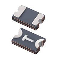
setP™ Temperature Indicators for USB Type-C
RoHS
Description
The Littelfuse setP™ temperature indicator helps
protect USB Type-C plugs from overheating. It has been
designed to the unique specifications of USB Type-C and
is capable of helping to protect even the highest levels
of USB Power Delivery.
Features
• Compact footprint:
0805 mils (2.0 x 1.2mm)
• Sensitive and reliable
temperature indication
• SMD compatible with
reflow soldering process
• Zero IR loss contribution
Agency Approvals
Agency
Agency File Number
Pending
• Easy part selection
• USB Power Delivery
compliant
• Protects systems with
100W or higher power
Pending
Applications
• �USB Type-C Plugs
• Chargers with captive
Type-C Cables
• Fast charging standards
and protocols compliant
with USB-C and USB-PD
Temperature Indication Characteristics
Part Number
Marking
SETP0805-100-SE
RT
Indicating Temperature (°C)
Min
90
Typical
100
1
Resistance (Ω)
Max
Max at 25°C 2
Rind 3
10
12
35,000
Notes:
1. Tind = Typical indicating temperature: Typical temperature when device switches to indicating resistance (Rind)
2. Maximum post reflow resistance measured at 25°C in still air
3. Rind = Indicating resistance when device reaches the indicating temperature (Tind)
© 2018 Littelfuse, Inc.
Specifications are subject to change without notice.
Revised: 07/12/18
�POLY-FUSE® Temperature Indicators
Surface Mount > setP™ Series
Electrical Characteristics
Part Number
Marking
Ihold 1
(A)
SETP0805-100-SE
RT
0.06
Itrip 2
(A)
Vmax 3
(Vdc)
Imax 4
(A)
0.25
6
1
Maximum
Time-To-Trip
Pd 5 typ.
(W)
Current Time
(A)
(Sec.)
0.6
0.3
1
Resistance
Rmin 6
(Ω)
R1max 7
(Ω)
0.5
12
Agency
Approvals
P
P
Notes:
1. Ihold = Hold current: maximum current device will pass without tripping in 20°C still air
2. Itrip = Trip current: minimum current at which the device will trip in 20°C still air
3. Vmax = Maximum voltage device can withstand without damage at rated current (Imax)
4. Imax = Maximum fault current device can withstand without damage at rated voltage (Vmax)
5. Pd = Power dissipated from device when in the tripped state at 20°C still air
6. Rmin = Minimum resistance of device in initial (un-soldered) state
7. R1max = Maximum resistance of device at 20°C measured one hour after tripping or reflow Soldering of 260°C for 20 seconds
(Values specified were determined using PCBs with 0.115in x 1.0in ounce copper traces)
Caution: Operation beyond the specified rating may result in damage and possible arcing and flame
Environmental Specifications
Percentage of Rated Current
Temperature Rerating Curve
170%
Operating Temperature
-40°C to +85°C
150%
Maximum Device Surface
Temperature in Tripped State
125°C
Passive Aging
+70°C, 1000 hours
-/+10% typical resistance change
Humidity Aging
+60°C, 85% R.H.,100 hours
-/+15% typical resistance change
Thermal Shock
MIL–STD–202, Method 215
No change
-40°C to +85°C, 10 Cycles
Solvent Resistance
MIL–STD–202, Method 215
No change
Vibration
MIL–STD–883, Method 2007,
Condition A No change
Moisture Sensitivity Level
Level 2a, J–STD–020
130%
110%
90%
70%
50%
30%
10%
-40
-30 -20
-10
0
10
20 30
40
Temperature (°C)
50
60
70
80
Physical Specifications
Terminal Material
Solder-Plated Copper
(Solder Material: Matte Tin (Sn))
Lead Solderability
Meets EIA Specification RS186-9E,
ANSI/J-STD-002, Category 3.
© 2018 Littelfuse, Inc.
Specifications are subject to change without notice.
Revised: 07/12/18
�POLY-FUSE® Temperature Indicators
Surface Mount > setP™ Series
Soldering Parameters
Profile Feature
Pb-Free Assembly
Average Ramp-Up Rate (TS(max) to TP)
3°C/second max
150°C
Temperature Max (Ts(max))
200°C
Time (Min to Max) (ts)
60 – 120 secs
Time Maintained Temperature (TL)
217°C
Above:
60 – 150 seconds
Temperature (tL)
tL
Ramp-do
Ramp-down
Preheat
TS(min)
tS
Peak / Classification Temperature (TP)
260
Time within 5°C of actual peak
Temperature (tp)
30 seconds max
Ramp-down Rate
2°C/second max
-- All temperature refer to topside of the package, measured on the package body surface
Time 25°C to peak Temperature (TP)
8 minutes Max.
-- If reflow temperature exceeds the recommended profile, devices may not meet the
performance requirements
+0/-5
°C
Critical Zone
tL to tP
Ramp-up
TL
TS(max)
Temperature
Pre Heat:
Temperature Min (Ts(min))
tP
TP
25
time to peak temperature
Time
-- Recommended reflow methods: IR, vapor phase oven, hot air oven, N2 environment for lead
-- Recommended maximum paste thickness is �0.25mm (0.010 inch)
-- Devices can be cleaned using standard industry methods and solvents
-- Devices can be reworked using the standard industry practices
Dimensions
Product Dimensions
Solder Pad Layout
Device Dimension
Part Number
A
B
inch
Min
mm
Max
Min
Max
inch
Min
Solder Pad
C
mm
inch
D
mm
E
inch
Max Min Max Min Max Min Max
Min
Max
mm
SIZE
INDICATING TEMP
SINGLE-END CABLE
© 2018 Littelfuse, Inc.
Specifications are subject to change without notice.
Revised: 07/12/18
- 0.027 -
0.69
G
H
inch mm inch mm inch mm
-
1.00 - 1.20 - 1.50
Packaging
SETP 0805 -100 -SE
SERIES
mm
Min Max Min Max Min Max
SETP0805-100-SE 0.079 0.087 2.00 2.20 0.017 0.025 0.43 0.60 0.051 0.079 1.30 2.00 0.017 0.087 0.43 2.20
Part Ordering Number System
inch
F
Part Number
Ordering
Number
Minimum
Order
Quantity
SETP0805-100-SE
RF4795-000
20,000
Packaging
Quantity
Option
Tape & Reel
4,000
�POLY-FUSE® Temperature Indicators
Surface Mount > setP™ Series
Installation and Handling Guidelines
• Operation of these devices beyond the stated maximum
ratings could result in damage to the devices and lead to
electrical arcing and/or fire.
• These devices are intended to protect against the effects
of temporary over-current or over-temperature conditions
and are not intended to perform as protective devices
where such conditions are expected to be repetitive or
prolonged in duration.
• Exposure to silicon-based oils, solvents, electrolytes, acids,
and similar materials can adversely affect the performance
of these PPTC devices.
• These devices undergo thermal expansion under fault
conditions, and thus shall be provided with adequate space
and be protected against mechanical stresses.
• Circuits with inductance may generate a voltage (L di/dt)
above the rated voltage of the PPTC device.
• Hand-soldering of PTC devices on boards is generally not
recommended. Users shall define and verify this process if
needed.
• Consult Littelfuse when the device is to be applied with
thermal processes other than reflow process on the
circuit board, such as molding, encapsulation. User should
evaluate molding materials used in the charging cable
applications to ensure there are no adverse effect on the
PTC devices.
Tape and Reel Specifications
SETP0805-100-SE
W
8.0 ± 0.30
P0
4.0 ± 0.10
P1
4.0 ± 0.10
P2
2.0 ± 0.05
A0
1.70 ± 0.10
B0
2.45 ± 0.10
B1 max.
4.35
D0
1.55 ± 0.05
F
3.50 ± 0.05
E1
1.75 ± 0.10
E2 min.
6.25
T max.
0.3
T1 max.
0.1
K0
0.86 ± 0.10
A max.
179
N min.
53.5
W1
9.5 ± 0.5
W2 max.
15
Standard Pack Quantity: 4,000 pcs
Minimum Order Quantity: 20,000 pcs
Disclaimer Notice - Information furnished is believed to be accurate and reliable. However, users should independently evaluate the
suitability of and test each product selected for their own applications. Littelfuse products are not designed for, and may not be used
in, all applications. Read complete Disclaimer Notice at www.littelfuse.com/disclaimer-electronics.
© 2018 Littelfuse, Inc.
Specifications are subject to change without notice.
Revised: 07/12/18
�
很抱歉,暂时无法提供与“SETP0805-100-SE”相匹配的价格&库存,您可以联系我们找货
免费人工找货