Next
Previous
Silicon Protection Circuits
Surface Mount SurgectorTM Transient Voltage Suppressors
Surgector Thyristors For Telecom Protection
Designed to suppress lightning and other transients, Surgector suppressors
are primarily intended for operation on the telephone line “tip and ring”
environment in order to protect telecommunications CPE and COE
products in conjunction with the Littelfuse 461 series Telecom Nano2® fuse.
These devices provide secondary protection for telecommunication
equipment such as telephone, MODEM, line card and other devices
subject to damage from transient over voltage events. Surgectors can be an
integral part of a Telephone Line Protector Unit, meeting AC Power Cross
criteria when used in association with properly selected resistor/ PTC/ fuse
combinations such as the Littelfuse 461 series fuse. Littelfuse Surface
Mount Surgectors are manufactured using a silicon thyristor technology,
offering bidirectional voltage clamping for transients of either polarity
from a single chip.
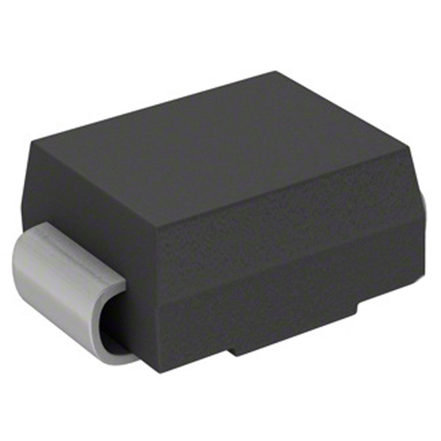
The Surgector devices described in this data sheet are manufactured
with the DO-214AA low profile case style and are second source
equivalent parts to industry “SIDAC” types. Surface Mount Surgector
Suppressors are supplied in embossed carrier tape on 330mm
(13in) reels.
Ordering Information
Features
• Rated for Telecom Industry Transient Surge Levels:
- Telcordia (Bellcore) GR-1089
- ITU CCITT K.20/.21
- FCC PART 68
- UL 60950
• Low Profile Package, Compatible with PCMCIA Cards, UL-94V-0 Listed
VBO (MAX)
ATIBO=800MA
(V)
IPP(MAX)
10 x 1000µs Pulse
(A)
IPP(MAX)
2 x 10µs Pulse
(A)
SGT0640SBT
77
50
320
SGT0720SBT
88
50
320
SGT2300SBT
260
50
200
SGT2900SBT
330
50
200
SGT3100SBT
350
50
200
SGT0640SCT
77
100
600
SGT0720SCT
88
100
600
SGT1300SCT
160
100
600
SGT1500SCT
180
100
600
SGT2300SCT
260
100
500
SGT2900SCT
330
100
500
SGT3100SCT
350
100
500
SGT3500SCT
400
100
500
PART
NUMBER
B TYPES
• Offered in the Most Common VDRM Voltage Types
• Low On-State Voltage
• Cross to Common Industry Types
• High Minimum Holding Current
AGENCY APPROVALS: Recognized under the components program of
Underwriters Laboratories.
AGENCY FILE NUMBERS: UL E135010.
Applications
C TYPES
NOTE: T Suffix indicates Tape and Reel.
• Secondary Protection for:
- DSL modem
- Set Top Box
- Telephone
- FAX
- Modem
- Line Cards
- SLIC
- TLPU Modules
• Alarm Systems
• CATV Lines
• Cable Modems
Symbol
236
®
w w w. l i t t e l f u s e . c o m
�Next
Previous
Silicon Protection Circuits
Surface Mount SurgectorTM Transient Voltage Suppressors
Surgector Thyristors For Telecom Protection
Absolute Maximum Ratings
Thermal Information
Continuous Reverse Voltage, VDRM . . . . . . . . . . . . . . . . . . . . . . . . . . . .58V to 300V
Thermal Resistance (Typical, Note 1)
θJA (oC/W)
J-Bend Package
C Types. . . . . . . . . . . . . . . . . . . . . . . . . . . . . . . . . . . . . . . . . . . . . . . . 85
B Type.. . . . . . . . . . . . . . . . . . . . . . . . . . . . . . . . . . . . . . . . . . . . . . . . . 90
Maximum Storage Temperature Range. . . . . . . . . . . . . . . . . . . . .- 65oC to 150oC
Maximum Junction Temperature (Plastic Package). . . . . . . . . . . . . . . . . . . . . 150oC
Maximum Lead Temperature (Soldering 5s). . . . . . . . . .. . . . . . . . . . . . . . . . . 300oC
Transient Peak Surge Current, IPP
B Types C Types
8 x 20µs
400A
200A
10 x 160µs
200A
150A
10 x 560µs
150A
100A
10 x 1000µs
100A
50A
Critical Rate of Rise of Voltage, dv/dt . . . . . . . . . . . . . . . . . . . . . . . . . . 2000V/µs
Operating Conditions
Temperature Range, (TA). . . . . . . . . . . . . . . . . . . . . . . . . . . . . . . . . -40oC to 85oC
CAUTION: Stresses above those listed in “Absolute Maximum Ratings” may cause permanent damage to the device. This is a stress only rating and operation of the device
at these or any other conditions above those indicated in the operational sections of this specification is not implied.
NOTE:
1. θJA is measured with the component mounted on an evaluation PC board in free air.
Electrical Specifications TC = 25oC, Unless Otherwise Specified
VT (MAX)
AT 2 A
VBO (MAX)
AT I BO = 800mA
(NOTE 2)
V
µA
V
SGT0640SBT
58
5
SGT0720SBT
63
5
SGT2300SBT
190
SGT2900SBT
SGT3100SBT
I H (MIN)
IPP (MAX) FOR 10
x 1000µs PULSE
(NOTE 3)
(NOTE 4)
CO (Typ)
AT 1MHz /
1VRMS,2VDC
V
mA
A
A
pF
5
77
150
50
25
80
5
88
150
50
25
80
5
5
260
150
50
25
30
250
5
5
330
150
50
25
30
275
5
5
350
150
50
25
30
SGT0640SCT
58
5
5
77
150
100
65
280
SGT0720SCT
63
5
5
88
150
100
65
280
SGT1300SCT
120
5
5
160
150
100
65
150
MODEL NUMBER
ITSM
B TYPES
C TYPES
SGT1500SCT
140
5
5
190
150
100
65
150
SGT2300SCT
190
5
5
260
150
100
65
100
SGT2900SCT
250
5
5
330
150
100
65
70
SGT3100SCT
275
5
5
350
150
100
65
70
SGT3500SCT
300
5
5
400
150
100
65
55
PERCENT OF PEAK VALUE
NOTES:
2. dv/dt = 100V/µs.
3. Double exponential current waveform.
4. One half cycle, 50 to 60Hz sine, non repetitive.
IT
IBO
IH
IDRM
VBO
VT
100
90
50
10
O1
T
T1
TIME
T2
O1 = Virtual Origin of Wave
T = Time From 10% to 90% of Peak
T1 = Virtual Front Time = 1.25 • t
T2 = Virtual Time to Half Value (Impulse Duration)
VDRM
Example: For an 8/20µs Current Waveform:
8µs = T1 = Virtual Front Time
20µs = T2 = Virtual Time to Half Value
FIGURE 2. PEAK PULSE CURRENT TEST WAVEFORM
FIGURE 1. V-I CHARACTERISTICS
w w w. l i t t e l f u s e . c o m
237
5
SILICON PROTECTION
CIRCUITS
VDRM (MAX)
IDRM (MAX)
AT V DRM
�Next
Previous
Silicon Protection Circuits
Surface Mount SurgectorTM Transient Voltage Suppressors
Surgector Thyristors For Telecom Protection
TABLE 1. ELECTRICAL CHARACTERISTICS
VARIATION OF
OF VBO vs TEMP
TA = -40oC TO 85oC
(%) (NOTE 5)
TYPICAL V T AT PEAK
I T, T A = 25oC VOLTS
(V) (NOTE 6)
VARIATION OF CO
vs
FREQUENCY
(%) (NOTE 7)
MAXIMUM CRITICAL
RATE OF RISE OF
ON-STATE CURRENT
(dl/dT) (A/ µs) (NOTE 8)
MAXIMUM I PP FOR
2x10µs WAVEFORM
(A)
(NOTE 9)
SGT0640SBT
-6 to +6
4.2 at 50A
1
120
320
SGT0720SBT
-6 to +6
4.2 at 50A
1
120
320
SGT2300SBT
-5 to +4
3.2 at 50A
1
120
200
SGT2900SBT
-4 to +4
3.3 at 50A
1
120
200
SGT3100SBT
-4 to +4
3.3 at 50A
1
120
200
SGT0640SCT
-6 to +6
5.2 at 100A
1
250
600
SGT0720SCT
-6 to +6
5.2 at 100A
1
250
600
SGT1300SCT
-5 to +1
4.1 at 100A
1
250
600
SGT1500SCT
-5 to +1
4.1 at 100A
1
250
600
SGT2300SCT
-5 to +4
4.9 at 100A
1
250
500
SGT2900SCT
-4 to +4
7.2 at 100A
1
250
500
SGT3100SCT
-4 to +4
7.2 at 100A
1
250
500
SGT3500SCT
-3 to +4
7.7 at 100A
2
250
500
MODEL
NUMBER
NOTES:
5. Typical percentage shift from normalized 25oC value (positive coefficient).
6. Typical maximum peak forward voltage drop at specified peak current.
7. Typical percentage shift with test frequency ranging from 1kHz to 1MHz/1VRMS (for two constant DC bias voltages of 0V and 50V).
8. dI/dT for leading edge of sine wave where 1/2 rated IPP is reached at initial 30o of the sine.
9. Rated IPP value for the 2x10µs waveform above which could cause device damage.
Typical Performance Curves
3.0
SGT2300SB
SGT0640SB
SGT0720SB
2.5
IH/IH AT 25 oC
2.0
1.5
1.0
0.5
0
-40
-20
0
20
40
60
80
100
NORMALIZED TO 25 oC VALUE
IH/IH AT 25 oC
NORMALIZED TO 25 oC VALUE
3.0
238
2.0
1.5
1.0
0.5
0
-40
120
-20
0
20
40
60
80
100
TEMPERATURE ( oC)
TEMPERATURE ( oC)
FIGURE 3. TYPICAL HOLDING CURRENT vs JUNCTION
TEMPERATURE
2.5
FIGURE 4. TYPICAL HOLDING CURRENT vs JUNCTION
TEMPERATURE
w w w. l i t t e l f u s e . c o m
120
�Next
Previous
Silicon Protection Circuits
Surface Mount SurgectorTM Transient Voltage Suppressors
Surgector Thyristors For Telecom Protection
Typical Performance Curves
(Continued)
2.5
3.0
SGT0640SC
SGT0720SC
2.0
IH/IH AT 25 oC
1.5
1.0
0.5
0
-40
-20
0
20
40
60
80
100
2.0
1.5
1.0
0.5
0
-40
120
0
40
TEMPERATURE ( oC)
FIGURE 5. TYPICAL HOLDING CURRENT vs JUNCTION
TEMPERATURE
IH/IH AT 25 oC
1.0
0.5
0
40
80
NORMALIZED TO 25 oC VALUE
IH/IH AT 25 oC
1.5
2.5
2.0
1.5
1.0
0.5
0
-40
120
-20
0
TEMPERATURE ( oC)
20
40
60
80
100
120
TEMPERATURE ( oC)
FIGURE 7. TYPICAL HOLDING CURRENT vs JUNCTION
TEMPERATURE
FIGURE 8. TYPICAL HOLDING CURRENT vs JUNCTION
TEMPERATURE
3.0
2.5
SGT3500SC
2.5
IH/IH AT 25 oC
2.0
1.5
1.0
0.5
-20
0
20
40
60
80
100
120
NORMALIZED TO 25 oC VALUE
SGT2900SC
SGT3100SC
IH/IH AT 25 oC
5
SGT2300SC
2.0
0
-40
NORMALIZED TO 25 oC VALUE
150
3.0
SGT1500SC
SGT1300SC
2.5
0
-40
120
FIGURE 6. TYPICAL HOLDING CURRENT vs JUNCTION
TEMPERATURE
3.0
NORMALIZED TO 25 oC VALUE
80
TEMPERATURE ( oC)
SILICON PROTECTION
CIRCUITS
IH/IH AT 25 oC
NORMALIZED TO 25 oC VALUE
2.5
NORMALIZED TO 25 oC VALUE
SGT2900SB
SGT3100SB
2.0
1.5
1.0
0.5
0
-40
TEMPERATURE ( oC)
-20
0
20
40
60
80
100
120
TEMPERATURE ( oC)
FIGURE 9. TYPICAL HOLDING CURRENT vs JUNCTION
TEMPERATURE
FIGURE 10. TYPICAL HOLDING CURRENT vs JUNCTION
TEMPERATURE
w w w. l i t t e l f u s e . c o m
239
�Next
Previous
Silicon Protection Circuits
Surface Mount SurgectorTM Transient Voltage Suppressors
Surgector Thyristors For Telecom Protection
Typical Performance Curves
(Continued)
1000
1000
SGT0640SB, SGT0720SB
f = 1MHz/1VRMS, TA = 25oC
SGT2300SB
f = 1MHz/1VRMS, TA = 25oC
CAPACITANCE (pF)
CAPACITANCE (pF)
500
100
50
10
0.1
101
1
100
10
0.1
00
1
BIAS (V)
FIGURE 11. TYPICAL CAPACITANCE vs BIAS VOLTAGE
1000
SGT2900SB, SGT3100SB
f = 1MHz/1VRMS, TA = 25oC
100
50
1
101
SGT0640SC, SGT0720SC
f = 1MHz/1VRMS, TA = 25oC
500
CAPACITANCE (pF)
CAPACITANCE (pF)
500
100
50
10
0.1
00
1
BIAS (V)
1000
SGT2300SC
f = 1MHz/1VRMS, TA = 25oC
SGT1300SC
f = 1MHz/1VRMS, TA = 25oC
CAPACITANCE (pF)
500
CAPACITANCE (pF)
00
FIGURE 14. TYPICAL CAPACITANCE vs BIAS VOLTAGE
1000
100
50
1
101
00
100
10
0.1
BIAS (V)
1
101
BIAS (V)
FIGURE 15. TYPICAL CAPACITANCE vs BIAS VOLTAGE
240
101
BIAS (V)
FIGURE 13. TYPICAL CAPACITANCE vs BIAS VOLTAGE
10
0.1
00
FIGURE 12. TYPICAL CAPACITANCE vs BIAS VOLTAGE
1000
10
0.1
101
BIAS (V)
FIGURE 16. TYPICAL CAPACITANCE vs BIAS VOLTAGE
w w w. l i t t e l f u s e . c o m
00
�Next
Previous
Silicon Protection Circuits
Surface Mount SurgectorTM Transient Voltage Suppressors
Surgector Thyristors For Telecom Protection
Typical Performance Curves
(Continued)
1000
1000
SGT2900SC,SGT3100SC
f = 1MHz/1VRMS, TA = 25oC
500
CAPACITANCE (pF)
100
50
10
0.1
1
101
100
50
10
0.1
00
1
BIAS (V)
101
00
BIAS (V)
FIGURE 17. TYPICAL CAPACITANCE vs BIAS VOLTAGE
FIGURE 18. TYPICAL CAPACITANCE vs BIAS VOLTAGE
5
SILICON PROTECTION
CIRCUITS
CAPACITANCE (pF)
500
SGT3500SC
f = 1MHz/1VRMS, TA = 25oC
Recommended Surgectors for Typical Industry Standard Transient Specifications
SPECIFIED PEAK
VOLTAGE
SPECIFIED PEAK
CURRENT
SPECIFIED CURRENT
WAVESHAPE
RECOMMENDED
SURGECTOR IPP TYPE
GR1089
600V
100A
10 x 1000µs
C
GR1089
1000V
100A
10 x 360µs
C
GR1089
1000V
100A
10 x 1000µs
C
GR1089
2500V
500A
2 x 10µs
C
GR 1089
1000V
25A
10 x 360µs
B, C
FCC PART 68
800V
100A
10 x 560µs
C
FCC PART 68
1500V
200A
10 x 160µs
C
FCC PART 68
1000V
25A
5 x 320µs
B, C
FCC PART 68
1500V
38A
5 x 320µs
B, C
ITU K.20
1000V
25A
5 x 310µs
B, C
ITU K.20
1000V
50A
5 x 310µs
B, C
ITU K.20
4000V
100A
5 x 310µs
C
ITU K.20
4000V
200A
5 x 310µs
C
ITU K.21
1500V
75A
5 x 310µs
B, C
ITU K.21
4000V
200A
5 x 310µs
C
ITU K.21
1000V
25A
5 x 310µs
B, C
ITU K.21
4000V
100A
5 x 310µs
C
INDUSTRY STANDARD
w w w. l i t t e l f u s e . c o m
241
�Next
Previous
Silicon Protection Circuits
Surface Mount SurgectorTM Transient Voltage Suppressors
Surgector Thyristors For Telecom Protection
Terms and Parameter Definitions
VDRM - Maximim Off-State Voltage (DC or Peak) which may be applied
continuously.
IDRM - Maximum Reverse Current measured with VDRM applied.
(Off-State Current)
IH - Minimum On-State Current required to maintain the device in the
latched-on state.
CO - Terminal Capacitance measured at the specified off-state bias Voltage.
ITSM - Maximum Peak Surge Current at the specified AC cycle waveform.
IPP - Peak Pulse Surge Current rating of a designated waveform.
VT - Forward Voltage drop at the specified Forward Current IT, in the
On-State latched mode.
VBO - Maximum Breakover Voltage at which the device switches to the
On-State latched mode.
Ordering Information
SGT 310
0
S
C
T
Peak Surge Current Indicator
B = 50A (10 x 1000)
C = 100A (10 x 1000)
Packing Method Option
T = 330mm Tape and Reel
2500 pieces per reel
Package Style
Single Die Indicator
Voltage Rating Class
Surgector
Tape and Reel Specifications (Meets EIA-481-1)
o
0
12
13 ±0.5
2 ±0.5
80
D
D = 330 ±2
LABEL
2 ±0.5
14 ±1.5
4.0 ±0.1
1.5
5.5 ±0.05
ROUND
FEED HOLE
2
1.75 ±0.1
TRAILER
DEVICE
TRAILER
START
END
12 ±0.3
9.5
40
8 ±0.1
242
LEADER
0.3
485 (MIN)
3.1 ±0.1
500 (MIN)
DIRECTION OF FEED
w w w. l i t t e l f u s e . c o m
�Previous
Silicon Protection Circuits
Surface Mount SurgectorTM Transient Voltage Suppressors
Surgector Thyristors For Telecom Protection
Mechanical Outline Dimensions and
Recommended Solder Pad Layout
Branding Layout
Littelfuse
SURGECTOR
DIMENSION: mm
3.75 ± 0.3
PEAK SURGE
CURRENT INDICATOR
2.0 ± 0.1
LF SC
2300 92
5.1 ± 0.3
2-DIGIT DATE CODE (YR/MTH)
4-DIGIT P/N REFERENCE
0.45
2.0 (MAX)
SGT2300SC (TOP VIEW - NOT TO SCALE)
Surface Mount Surgectors may be soldered with wave or reflow methods,
and are compatible with common industry time-temperature profiles that
include a preheat stage. When hand soldering, a 30W iron with a 1mm
tip is recommended. The temperature should not exceed 300oC or a
maximum 5 second duration.
1.0 ± 0.3
0.1 ± 0.1
1.78
0.1 ± 0.1
2.29
1.78
5
SILICON PROTECTION
CIRCUITS
1.0 ± 0.3
Soldering Recommendations
2.29
SOLDERING PAD
w w w. l i t t e l f u s e . c o m
243
�
很抱歉,暂时无法提供与“SGT3100SBT”相匹配的价格&库存,您可以联系我们找货
免费人工找货- 国内价格 香港价格
- 5000+2.754835000+0.35659