Gas Discharge Tube (GDT) Products
SL1011A/B and SL1411A Series
SL1011A/B and SL1411A Series
®
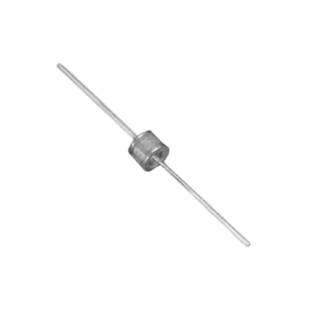
Description
The SL1011A/B and SL1411A series provides high
levels of protection against fast rising transients
in the 100V/μs to 1kV/μs range usually caused by
lightning disturbances.
The SL1011A/B and SL1411A series offers low
capacitance (< 1.5pf) which provides low insertion
loss at high frequencies.
SL1011A offers 5kA protection without destruction
whereas the SL1011B and SL1411A offer 10kA surge
protection without destruction (maximum single
surge of 12kA @ 8/20μs).
Agency Approvals
AGENCY
®
Features
AGENCY FILE NUMBER
• RoHS compliant
• Low insertion loss
• Excellent response to
fast rising transients
• Ultra low capacitance
E128662
2 Electrode GDT Graphical Symbol
• 5kA (SL1011A) or 10kA
(SL1011B & SL1411A)
surge capability tested
with 8/20μs
pulse as defined by
IEC 61000-4-5
Applications
• Broadband equipment
• ADSL equipment
• XDSL equipment
©2010 Littelfuse, Inc.
Specifications are subject to change without notice.
Please refer to www.littelfuse.com for current information.
Customer should verify actual device performance in their specific applications.
47
Revised: June 28, 2010
• Satellite and CATV
equipment
• General telecom
equipment
SL1011A/B and SL1411A Series
�Gas Discharge Tube (GDT) Products
SL1011A/B and SL1411A Series
Electrical Characteristics
Device Specifications (at 25°C)
Part Number
Life Ratings
Impulse
Impulse Insulation CapaciDC Breakdown
Breakdown Breakdown Resistance tance
in Volts1,2
in Volts3
In Volts
(@100V/s)
(@1MHz)
(@100V/μs)
MIN
TYP
MAX
MAX
��
��
��
���
(@1kV/μs)
MIN
MAX
Arc
Voltage
Surge
Life
(on state
(@100A
Voltage)
10/1000μs)
@1Amp Min
Nominal
Impulse
Discharge
Current
Nominal
AC
Discharge
Current
(8/20μs)
(10x1s
@50-60Hz)
AC
Dischage
Current
DC
Holdover
Voltage4
Max Impulse
Discharge Current
(1 Application)
(9 Cycles @
50Hz)
TYP
TYP
@ 8/20μs
@ 10/350μs
6/����%�
�
6/����$��
���N$
��N$�
6/����$���
6/����%���
���
6/����$���
�����ȍ
�DW���9�
6/����$���
6/����%���
��
��
���
���
���
��� ��� ���
���
���
��� ��� ���
���
���
���9
6/����$���
6/����$���
6/����%���
6/����$���
6/����%���
6/����$��
���VKRWV�
�#�N$�
6/����$���
6/����%��� ��� ��� ���
���
���
6/����$���
����S)
6/����$���
6/����%��� ��� ��� ���
���
6/����%���
���
VKRWV
���
�����ȍ
�DW����9�
6/����$���
6/����$���
a���9
��� ��� ���
���
6/����$��
��$
6/����$��
���$
6/����%� � 6/����%� � 6/����%� �
6/����$��
6/����$��
6/����$��
���VKRWV�
���$
���$
�#��N$�
���
����9
6/����$���
6/����%��� ��� ��� ���
���
���
��� ��� ���
����
����
6/����$��� ��� ��� ���
����
����
����
����
6/����$���
6/����$���
6/����$���
6/����$���
6/����$���
��� ��� ���
Notes:
1. At delivery AQL 0.65 level II, DIN ISO 2859
2. In ionized mode
3. Comparable to the silicon measurement Switching Voltage (Vs)
4. Tested according to ITU-T Rec. K.12 < 150 msecs.
Product Characteristics
Materials
Leaded Device: Nickel-plated with Tinplated wires
Core and Surface Mount: Dull Tin-plated
Product Marking
Littelfuse 'LF' Mark, voltage and date
code
SL1011A/B and SL1411A Series
Glow to Arc
Transition Current
< 0.5 Amps
Glow Voltage
~60 Volts
Storage and
Operational
Temperature
-40 to +90°C
48
Revised: June 28, 2010
©2010 Littelfuse, Inc.
Specifications are subject to change without notice.
Please refer to www.littelfuse.com for current information.
Customer should verify actual device performance in their specific applications.
�Gas Discharge Tube (GDT) Products
SL1011A/B and SL1411A Series
Device Dimensions
For SL1011A/SL1011B series:
'C' Type Core Devices
'A' Type Axial Lead Devices
PROFILE VIEW
TOP VIEW
TOP VIEW
PROFILE VIEW
Ø8.0 ± 0.2
[0.315 ± 0.0079]
Ø0.8
[0.031]
Ø8.0 ± 0.2
Ø8.0 ± 0.2
[0.315 ± 0.0079]
SEMI–PROFILE VIEW
6.05 ± 0.2
[0.238 ± 0.0079]
6.05 ± 0.2
[0.238 ± 0.0079]
62 ± 2
For SL1411A series:
'A' Type Axial Lead Devices
PROFILE VIEW
'SM' Type Surface Mount Devices
TOP VIEW
TOP VIEW
PROFILE VIEW
8.3 ± 0.1
4 [0.157]
Ø1.0
[0.039]
+ 0.10
Ø8.0 – 0.30
0.0039
[0.315 +
– 0.0118 ]
SEMI–PROFILE VIEW
5.55 [0.219]
Ø8.3 ± 0.15
6.05 ± 0.2
[0.238 ± 0.0079]
6.05 ± 0.2
[0.238 ± 0.0079]
9.
Ø
62 ± 2
30
0.5 ± 0.1
±
2
0.
SOLDER PAD LAYOUT
1.30 [0.051]
'C' Type Core Devices
7.00 [0.276]
TOP VIEW
PROFILE VIEW
+ 0.10
Ø8.00 – 0.30
0.0039
[0.315 +
– 0.0118 ]
SEMI–PROFILE VIEW
+ 0.20
6.05 – 0.15
0.0079
[0.238 +
– 0.0059 ]
+ 0.10
Ø8.00 – 0.30
5.40 [0.213]
©2010 Littelfuse, Inc.
Specifications are subject to change without notice.
Please refer to www.littelfuse.com for current information.
Customer should verify actual device performance in their specific applications.
49
Revised: June 28, 2010
SL1011A/B and SL1411A Series
�Gas Discharge Tube (GDT) Products
SL1011A/B and SL1411A Series
Soldering Parameters - Reflow Soldering (Surface Mount Devices)
Pre Heat
Pb-free assembly
Critical Zone
TL to TP
Ramp-up
- Temperature Min (Ts(min))
150°C
- Temperature Max (Ts(max))
200°C
- Time (Min to Max) (ts)
60 – 180 seconds
Average Ramp-up Rate (Liquidus Temp
(TL) to peak)
3°C/second max.
TS(max) to TL - Ramp-up Rate
5°C/second max.
Reflow
tP
TP
- Temperature (TL) (Liquidus)
217°C
- Temperature (tL)
60 – 150 seconds
TL
TS(max)
Temperature
Reflow Condition
tL
Ramp-down
Preheat
TS(min)
tS
25
Peak Temperature (TP)
260+0/-5 °C
Time within 5°C of Actual Peak
Temperature (tp)
10 – 30 seconds
Ramp-down Rate
6°C/second max.
Time 25°C to Peak Temperature (TP)
8 minutes max.
Do not exceed
260°C
time to peak temperature
(t 25ºC to peak)
Time
Soldering Parameters - Wave Soldering (Thru-Hole Devices)
Recommended Process Parameters:
280
Wave Parameter
260
240
Lead-Free Recommendation
Preheat:
220
(Depends on Flux Activation Temperature)
200
180
160
140
120
100
60
(Typical Industry Recommendation)
Temperature Minimum:
100° C
Temperature Maximum:
Preheat Time:
150° C
60-180 seconds
Solder Pot Temperature:
280° C Maximum
Solder Dwell Time:
2-5 seconds
80
40
240
230
220
210
200
190
180
170
160
150
140
130
120
110
90
100
80
70
60
50
40
20
0
0
30
20
10
Temperature (°C) - Measured on bottom side of board
300
Time (Seconds)
Cooling Time
Preheat Time
Dwell Time
Soldering Parameters - Hand Soldering
Solder Iron Temperature: 350° C +/- 5°C
Heating Time: 5 seconds max.
SL1011A/B and SL1411A Series
50
Revised: June 28, 2010
©2010 Littelfuse, Inc.
Specifications are subject to change without notice.
Please refer to www.littelfuse.com for current information.
Customer should verify actual device performance in their specific applications.
�Gas Discharge Tube (GDT) Products
SL1011A/B and SL1411A Series
Packaging Dimensions
For 'A' Type Axial Lead Items
Dimensions are in millimeters [and inches]
Dimensions are in millimeters [and inches]
< 1.2 Max. Lead Bend
254.0 - 356.0
[10.0 - 14.0]
< 0.7 Max.
Direction of Feed
77.0 Max.
[3.03]
52.4 +2
–1
[2.063 +0.079
–0.039 ]
22.8
[0.898]
6±1
[0.236 ± 0.039]
10 ± 0.5 Pitch
[0.394 ± 0.020]
For 'SM' Type Surface Mount Items (SL1411A series only)
Dimensions are in millimeters [and inches]
Dimensions are in millimeters [and inches]
275.0
[10.83]
10x4 ± 0.1 = 40 ± 0.2
[10x0.157 ± 0.004 = 1.575 ± 0.008]
0.4 ± 0.05
[0.016 ± 0.002]
1.75 ± 0.1
[0.069 ± 0.004]
100.0
[3.94]
4 ± 0.1
[0.157 ± 0.004]
1.5 DIA. MAX.
[0.059]
76.0
[2.99]
25.0
[0.98]
7.5 ± 0.1
[0.295 ± 0.004]
8.5 ± 0.1
[0.335 ± 0.004]
17.7
[0.697]
16 +0.3 / -0.1
[0.630 +0.012 / -0.004]
Direction of Feed
8.6 ± 0.1
[0.339 ± 0.004]
1.5 DIA. MAX.
[0.059]
12 ± 0.1
[0.472 ± 0.004]
For 'C' Type Core Items: Packed in plastic bag (500 pcs)
©2010 Littelfuse, Inc.
Specifications are subject to change without notice.
Please refer to www.littelfuse.com for current information.
Customer should verify actual device performance in their specific applications.
51
Revised: June 28, 2010
SL1011A/B and SL1411A Series
�Gas Discharge Tube (GDT) Products
SL1011A/B and SL1411A Series
Part Numbering System and Ordering Information
For SL1011A series:
SL1011A XXX X
Voltage
Pin Configuration
A = Axial Lead
C = Core
Remarks: Formed leads are available on request
For SL1011B series:
SL1011B XXX X
Voltage
Pin Configuration
A = Axial Lead
C = Core
Remarks: Formed leads are available on request
For SL1411A series:
SL1411 A XXX XX
Surge Capability
Voltage
Pin Configuration
A = Axial Lead
C = Core
SM = Surface Mount
SL1011A/B and SL1411A Series
52
Revised: June 28, 2010
©2010 Littelfuse, Inc.
Specifications are subject to change without notice.
Please refer to www.littelfuse.com for current information.
Customer should verify actual device performance in their specific applications.
�
很抱歉,暂时无法提供与“SL1011B250A”相匹配的价格&库存,您可以联系我们找货
免费人工找货