物料型号:Littelfuse的TVS二极管,SMCJ系列。
器件简介:SMCJ系列是专为保护敏感电子设备免受雷电和其他瞬态电压事件引起的电压瞬态而设计的。
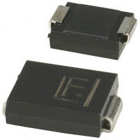
引脚分配:文档中没有明确提到引脚分配,但提到了器件为表面贴装应用设计,以优化板空间。
参数特性:
- 1500W的峰值脉冲功率能力,在10/1000μs波形下,重复率(占空比)为0.01%。
- 出色的钳位能力。
- 快速响应时间:从0V到BV最小值典型小于1.0ps。
- 玻璃钝化芯片结。
- 高温度至260°C/30秒的回流焊接保证。
功能详解:
- 低增量浪涌阻抗。
- 典型IR小于1μA,当VBR最小值大于12V时。
- 典型故障模式是因电压或电流过规格而短路。
- 须毛测试基于JEDEC JESD201A进行。
- 符合IEC 61000-4-2标准的ESD 30kV(空气),30kV(接触)。
- 符合IEC 61000-4-2标准的数据线ESD保护。
- 符合IEC 61000-4-4标准的数据线EFT保护。
应用信息:TVS器件非常适合用于电信、计算机、工业和消费电子应用中的I/O接口、VCC总线和其他易损电路的保护。
封装信息:
- 低轮廓封装。
- 内置的应变缓解。
- 塑料封装的阻燃等级为V-0,根据Underwriters Laboratories标准。
- 符合J-STD-020标准的MSL等级1,LF最大峰值为260°C。
- 无铅镀锡。
- 无卤素,符合RoHS标准。
电气特性表提供了不同型号的TVS二极管的详细电气参数,包括反向立电压、击穿电压、测试电流、最大钳位电压、最大峰值脉冲电流和最大反向漏电流等。