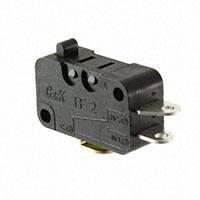
TF2 Series
Mid Size Snap-acting Switches
Features/Benefits
• ��Broad range of operating forces
• Ratings up to 10 AMPS
• Wide variety of actuator styles
• �Quick connect terminations
Snap-acting
J
Typical Applications
• ��Motor controls
• Thermostatics
• Portable tools
• Air Conditioner
Specifications
Materials
CONTACT RATING: From low level* to 10 AMPS @125/250 V AC.
ELECTRICAL LIFE: 10,000 cycles
MECHANICAL LIFE: 1,000,000 cycles at 0.1A and 6A
400,000 cycles at 10A
INSULATION RESISTANCE: 1,000 M ohm min.
DIELECTRIC STRENGTH: 1,500 Vrms min. @ sea level.
OPERATING TEMPERATURE: –40ºC to 125ºC (–40ºC to 85ºC).
OPERATING FORCE: From 18 to 330 grams at actuator
button available.
MOUNTING: Torque screws 2-5 in/lbs.
SWITCH HOUSING: Nylon 6/6
ACTUATOR BUTTON: Nylon 6/6
SPRING: Stainless Steel
PIVOT: Brass Alloy
MOVABLE CONTACTS: See electric rating page J-21
MOVABLE BLADE: BeCu
STATIONARY CONTACTS: See electric rating page J-21
TERMINALS: Brass Alloy
NOTE: Specifications and materials listed above are switches with standard options.
For information on specific and custom switches, consult Customer Service Center.
* Low Level=conditions where no arcing occurs during switching, i.e., 0.4 VA max. @
20 V AC or DC max. Standard electrical life per UL 1054, rated for 6,000 operations.
Build-A-Switch
To order, simply select desired option from each category and place in the appropriate box. For additional options not shown in
catalog, consult Customer Service Center.
T
Series
TF2
F
2
SP, Mom.
Operating Force
CC 18 grams
CF 45 grams
Electrical Rating Chart
CG 75 grams
CH 110 grams
OPTION
CODE
CJ 170 grams
61058-1
EC 230 grams
0.1A 125/250 V AC (T85)
F5
EE 330 grams
Min. 10,000 operations
0.1A 125/250 V AC
µT125, 1E4
H8
6A 125/250 V AC (T85)
Min. 10,000 operations
6A 125/250 V AC
K6
10A 125/250 V AC (T85)
Min. 10,000 operations
10(4)A 125/250 V AC
Mounting Style
S Standard
V Metric
µT125, 1E4
µT125, 1E4
see chart on following pages of compatible electrical ratings
and operating force options
* Note: No UL & ENEC 15 safety for Termination option “60”
Actuator
P00 Pin plunger
A10 Lever roller 12.5 mm
A15 Lever roller 25.9 mm
A20 Lever roller 12.5 mm
A25 Lever roller 25.9 mm
T10 Lever 14 mm
T14 Simulated roller 24.5 mm
T15 Lever 27.5 mm
T16 Lever 31.7 mm
T17 Lever 35 mm
T20 Lever 14 mm
T24 Simulated lever 24.5 mm
T25 Lever 27.5 mm
T26 Lever 31.7 mm
T27 Lever 35 mm
Circuitry
C SPDT
W SPST N.C.
Y SPST N.O.
Terminations
40 .187” quick connect
4A .250” quick connect
5A .250” off set quick connect
5B .187” off set quick connect
60 Screw style *
10 Solder
see chart on following pages for
detailed information
Dimensions are shown: mm
Specifications and dimensions subject to change
4 Jul 22
J–88
www.ckswitches.com
�TF2 Series
Mid Size Snap-acting Switches
SERIES
TF2 MID SIZE SNAP-ACTING SWITCHES
1.094
[27,8]
.406
[10,3]
.165
[4,2]
.110
[2,8]
.795
[20,2]
.626
[15,9]
.110
[2,8]
.406
[10,3]
.579 OPERATING
POSITION
[14,7]
.874
[22,2]
OPERATING FORCE
OPTION CODE
BASIC SWITCH
OPERATING FORCE (grams)
CC
18
CF
45
CG
75
CH
110
CJ
170
EC
230
EE*
330
J
Snap-acting
*Minimums may apply, consult Customer Service Center.
ELECTRICAL RATING
CONTACT MATERIAL
OPTION CODE
RoHS
COMPLIANT *
RoHS
COMPATIBLE *
F5
Yes
Yes
H8
Yes
Yes
K6
Yes
Yes
MOVABLE
CONTACT
STATIONARY
CONTACT
Silver alloy
Silver alloy
* Note: See Technical Data section of this catalog for RoHS compliant and compatible definitions and specifications.
All models
Third Angle
Projection
Dimensions are shown: inches (mm)
Specifications and dimensions subject to change
4 Jul 22
J–89
www.ckswitches.com
�TF2 Series
Mid Size Snap-acting Switches
ELECTRICAL RATING
INTERNATIONAL RATING SYMBOLS
µ
Microgap construction
(less than 3 mm).
~
Alternating current.
J
AMPS
(REF.)
F5
Maximum rated use temperature.
T_ _
OPERATING FORCE
ELECTRICAL
RATING
50E3
Cycles over 50,000 at rated current.
10E3
Cycles over 10,000 at rated current.
10(3)
Current Rating: First number
represents resistive rating; second
number represents inductive
(motor) rating.
CC
CF CG CH
CJ
EC
EE
(18) (45) (75) (110) (170) (230) (330)
0.1 • • • • • • X
H8
6
X • • • • • •
K6
10
X X X • • • •
• AVAILABLE
x NOT AVAILABLE
All models
Snap-acting
Consult Customer Service center for availability and delivery of
nonstandard ratings.
* Low Level=conditions where no arcing occurs during switching, i.e.,
0.4 VA max. @ 20 V AC or DC max.
MOUNTING STYLE
S STANDARD
V �Metric
For 4-40 screw size
For 3 mm screw size
.122
[3,1]
.114
[2,9]
.122
[3,1]
.114
[2,9]
.134
[3,4]
.126
[3,2]
TF2 SWITCH WITH TYPE 40 (.187 QC) TERMINALS
AND P00 ACTUATOR SHOWN
TF2 SWITCH WITH TYPE 10 (SOLDER) TERMINALS
AND P00 ACTUATOR SHOWN
NOTE: TORQUE MOUNTING SCREWS 2-5 IN/LBS.
NOTE: TORQUE MOUNTING SCREWS 2-5 IN/LBS.
Third Angle
Projection
Dimensions are shown: inches (mm)
Specifications and dimensions subject to change
4 Jul 22
J–90
www.ckswitches.com
�TF2 Series
Mid Size Snap-acting Switches
ACTUATOR
OPTION
FIG
CODE
DIM. A
DIM. B
-
P00
2
.795
(20,2)
A10
1
.822
(20,9)
A15
1
A20
DIM. C
DIM. D
DIM. E
.578
(14,70
.019
0,05)
0.068
(1.72)
.33
(8,4)
.816
(20,73
.050
1,27)
.106
(2,70)
(
.19
4,8)
1.35
(34,3)
.33
(8,4)
.816
(20,73
.059
1,5)
.165
(4,20)
(
.19
4,8)
1
1.05
(26,8)
.56
(14,3)
.816
(20,73
.050
1,27)
.183
(4,65)
(
.19
4,8)
A25
1
1.58
(40,2)
.56
(14,3)
.816
(20,73
.086
2,2)
.366
(9,30)
(
.19
4,8)
T10
3
.882
(22,39)
.33
(8,4)
.602
(15,3
.020
0,50)
.110
(2,80)
T14
4
1.295
(32,9)
.33
(8,4)
.737
(18,72
.059
1,5)
.216
(5,50)
T15
3
1.405
(35,69)
.33
(8,4)
.600
(15,24
.059
1,5)
.232
(5,90)
-
T16
3
1.58
(40,01)
.33
(8,4)
.604
(15,35
.068
1,75)
.196
(5,0)
-
T17
3
1.708
(43.39)
.33
(8,4)
.603
(15,33
.062
1.57)
.216
(5,50)
-
T20
3
1.11
(28,3)
.56
(14,3)
.604
(15,34
.045
1,14)
.204
(5,20)
-
T24
4
1.527
(38,8)
.56
(14,3)
.742
(18,84
.090
2,29)
.342
(8,70)
T25
3
1.631
(41,43)
.56
(14,3)
.609
(15,47
.090
2,3)
.381
(9,70)
-
T26
3
1.811
(46,00)
.56
(14,3)
.616
(15,65
.125
3.18)
.389
(9,90)
-
T27
3
1.94
(49,3)
.56
(14,3)
.598
(15,2
.150
3.8)
.433
(11,0)
-
-
(
J
Snap-acting
(
.275
7,0)
.275
7,0)
NOTE: Switch characteristics chart on following page.
Lever Roller
Pin Roller
DIM.A
DIM.B
DIM.E
DIM.D
DIM.D
DIM.A
DIM.C
DIM.C
FIG. 2
PIN ROLLER
TF2XXXXMP0010C
FIG. 1
LEVER ROLLER
TF2XXXXMA1510C
Lever
Simulated Roller
DIM.B
DIM.A
DIM.A
DIM.B
DIM.E
DIM.D
DIM.D
DIM.C
DIM.C
FIG. 4
SIMULATED ROLLER
TF2XXXXST1410C
FIG. 3
LEVER
TF2XXXXST1510C SHOWN
Dimensions are shown: inches (mm)
Specifications and dimensions subject to change
4 Jul 22
J–91
www.ckswitches.com
�TF2 Series
Mid Size Snap-acting Switches
ACTUATOR
Lever Type
P00
T10
T20
T14
T24
A10
Snap-acting
J
A20
A15
A25
T17
T27
T16
T26
T15
T25
CC
CF
CG
CH
Grams
CJ
EC
EE
OF
18
45
75
110
170
230
330
RF
3
7
14
20
34
42
60
OF
18
45
75
110
170
230
330
RF
-
6
11
17
25
35
50
OF
8
27
43
50
85
120
175
RF
-
3
5
7
13
17
25
OF
10
28
43
65
110
140
205
RF
-
3
5
8
14
17
31
OF
7
16
24
35
56
70
100
RF
-
-
-
4
5
9
12
OF
20
55
80
110
170
230
330
RF
-
5
11
16
28
31
45
OF
8
35
55
70
100
120
175
RF
-
3
5
7
14
18
28
OF
8
30
45
65
100
125
180
RF
-
-
5
7
12
16
25
OF
7
20
30
40
51
65
90
RF
-
-
-
-
6
8
9
OF
16
25
35
50
80
100
140
RF
-
2
4
6
11
14
20
OF
13
18
24
32
45
55
90
RF
-
-
2
3
5
7
10
OF
15
17
32
55
85
110
150
RF
-
-
4
6
12
15
22
OF
10
12
18
35
45
65
90
RF
-
-
2
4
6
8
11
OF
18
22
37
50
86
125
180
RF
-
3
5
9
14
17
24
OF
5
16
25
30
51
65
RF
-
-
3
4
6
8
Max
Pre-Travel
Over Travel
Differential
max. mm
Min. mm
max. mm
1.72
0.4
0.8
2.8
0.5
0.6
5.2
0.9
1.55
5.5
1.1
1.4
8.7
1.7
3.2
2.7
0.45
0.6
4.65
0.8
1.4
4.2
1.25
1.6
9.3
1.8
2.8
5.5
1.2
0.55
11
2.3
3.6
5
1.05
1.8
9.9
2.05
3.6
5.9
1
1.6
90
11
2.2
3.1
LOW FORCE, HIGH MOTION PIVOT POSITION
HIGH FORCE, LOW MOTION PIVOT POSITION
.548
[13,93]
.440
[11,17]
Available with actuators A20, A25, T20, T23, T24, T25, T26, and T28.
Available with actuators A10, A15, T10, T13, T14, T15, T16 and T18.
NOTE: Lever actuator options are available in either of two pivot positions.
Levers located in the forward pivot position have lower forces and higher motions.
Levers located in the rear pivot position have higher forces and lower motions.
4 Jul 22
9.7
J–92
Dimensions are shown: mm
Specifications and dimensions subject to change
www.ckswitches.com
�TF2 Series
Mid Size Snap-acting Switches
TERMINATIONS
40 .187” QUICK CONNECT
4A .250” QUICK CONNECT
.055
[1,4]
.126
[3,2]
.551
[14]
.248
[6,3]
.185
[4,7]
.508
[12,9]
.236
[6]
26°
.406
[10,31]
.629
[15,98]
REF
.031TYP
[0,8]
.020 TYP
[0,5]
.264
[6,7]
.098
[2,5]
.165
[4,2]
5A .250” OFF SET QUICK CONNECT
5B .187” OFF SET QUICK CONNECT
.452
[11,49]
.413
[10,49]
.071 TYP
[1,8]
.187
[4,75]
.279
[7,09]
.248
[6,3]
.248
[6,3]
.350
[8,9]
.350
[8,9]
.629
[15,98]
REF
.031 TYP
[0,8]
.264
[6,7]
.098
[2,5]
60 SCREW STYLE
.629
[15,98]
REF
.224
[5,7]
.098
[2,5]
10 SOLDER
4-40 X .125
(3,18)
TYP.
SCREWS &
LOCKWASHERS
.098
[2,5]
TYP
.295
[7,5]
.295
[7,5]
.236
[6]
.236
[6]
.031
[0,8]
.390
[9,9]
.031 TYP
[0,8]
.390
[9,9]
CIRCUITRY
C
W
Y
SPDT (Single Pole, Double Throw)
SPST N.C. (Single Pole, Single Throw, Normally Closed)
SPST N.O. (Single Pole, Single Throw, Normally Open)
Dimensions are shown: inches (mm)
Specifications and dimensions subject to change
4 Jul 22
J–93
www.ckswitches.com
Snap-acting
.578
[14,69]
.578
[14,69]
.031 TYP
[0,8]
J
.055 TYP
[1,4]
�