Metal-Oxide Varistors (MOVs)
Industrial High Energy Terminal Varistors > BA/BB Series
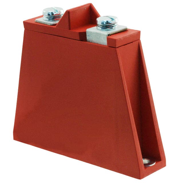
BA/BB Varistor Series
RoHS
Description
BB Series
The BA and BB Series transient surge suppressors are
heavy-duty industrial Metal-Oxide Varistors (MOVs)
designed to provide surge protection for motor controls and
power supplies used in oil-drilling, mining, transportation
equipment and other heavy industrial AC line applications.
BA Series
Both the BA and BB Series feature improved creep and
strike capability to minimize breakdown along the package
surface, a package design that provides complete electrical
isolation of the disc subassembly, and rigid terminals to
ensure secure wire contacts.
Agency Approvals
Agency
These varistors have similar package construction but differ
in size and ratings. The BA models are rated from 130 to
880VM(AC). The BB models from 1100 to 2800VM(AC).
Agency Approval
Agency File Number
UL1449
E320116 - for BA Series only.
Additional Information
See BA/BB Series Device Ratings and Specifications Table
for part number and brand information.
Features
• High energy absorption
capability WTM
BA Series 3200J
Datasheet
BA
Resources
BA
Samples
BA
BB Series 10,000J
• Wide operating voltage
range VM(AC)RMS
BA Series 130V to 880V
Datasheet
BB Series 1100V to 2800V
Resources
Samples
• Case design provides
complete electrical isolation
of disc subassembly
• Littelfuse largest packaged
disc 60mm diameter
• No derating up to 85ºC
ambient
• RoHS compliant
• Rigid terminals for secure
wire contact
Absolute Maximum Ratings
• For ratings of individual members of a series, see Device Ratings and Specifications chart
Continuous
BA Series
BB Series
Units
Steady State Applied Voltage:
AC Voltage Range (VM(AC)RMS)
130 to 880
1100 to 2800
V
DC Voltage Range (VM(DC))
175 to 1150
1400 to 3500
V
50,000 to 70,000
70,000
A
Transients:
Peak Pulse Current (ITM)
For 8/20µs Current Wave (See Figure 2)
Single Pulse Energy Range
For 2ms Current Squarewave (WTM)
450 to 3200
3800 to 10000
Operating Ambient Temperature Range (TA)
-55 to +85
-55 to +85
O
Storage Temperature Range (TSTG)
-55 to +125
-55 to +125
O
BA/BB Series
Peak Pulse Current Test Waveform
PERCENT OF PEAK VALUE
Power Dissipation Ratings
PERCENT OF RATED VALUE
100
90
80
70
60
50
40
30
20
50
60
70
80
90
100
110
120
130
50
Should transients occur in rapid succession, the average power
dissipation required is simply the energy (watt-seconds) per pulse
times the number of pulses per second. The power so developed
must be within the specifications shown on the Device Ratings
and Characteristics Table for the specific device. Furthermore,
the operating values need to be derated at high temperatures as
shown in the above diagram. Because varistors can only dissipate
a relatively small amount of average power they are, therefore, not
suitable for repetitive applications that involve substantial amounts
of average power dissipation.
Stand by Power Dissipation vs Applied VRms at Varied
Temperatures
Typical Stability of Standby Power Dissipation at Rated
VRMS vs Time
0.5
POWER DISSIPATION (W) PER kV
OF RATED V RMS
POWER DISSIPATION (W) PER kV
OF RATED V RMS
1,000 HOURS, TA = 85oC
0.6
0.4
MAX AT TA = 25oC
0.1
0.08
TYP AT TA = 25oC
0.06
0.04
80
90
100
110
FIGURE 3. STANDBY POWER DISSIPATION vs APPLIED
VRMS AT VARIED TEMPERATURES
0.4
0.3
0.2
0.1
0
PERCENTAGE OF MAXIMUM RATED V RMS (%)
Figure 3
T2
01 = Virtual Origin of Wave
T = Time from 10% to 90% of Peak
T1 = Rise Time = 1.25 x T
T2 = Decay Time
Example - For an 8/20 µs Current Waveform:
8µs = T1 = Rise Time
20µs = T2 = Decay Time
MAX AT TA = 85oC
0.2
TIME
FIGURE 2. PEAK PULSE CURRENT TEST W
TYPICAL TEMPERATURE COEFFICIENT
OF POWER DISSIPATION = 2.2%/ oC
1.0
0.8
T
T1
Figure 2
FIGURE 1. CURRENT, ENERGY AND POWER DERATING
CURVE
Example: For an 8
8 s = T 1 = Virtua
20 s = T 2 = Virtual
10
140 150
AMBIENT TEMPERATURE ( oC)
Figure 1
O1 = Virtual Orig
T = Time From
T 1 = Virtual Fron
T 2 = Virtual Time
90
O1
10
0
-55
100
Figure 4
0
10
100
TIME AT RATED V RMS (HOURS)
1,000
FIGURE 4. TYPICAL STABILITY OF STANDBY POWER
DISSIPATION AT RATED V RMS vs TIME
© 2020 Littelfuse, Inc.
Specifications are subject to change without notice.
Revised: BO.12/10/20
�Metal-Oxide Varistors (MOVs)
Industrial High Energy Terminal Varistors > BA/BB Series
Maximum Clamping Voltage BA Series
Maximum Clamping Voltage BB Series
V131BA60 - V881BA60
30,000
MAX CLAMPING VOLTAGE
DISC SIZE 60mm
130 TO 880VM(AC) RATING
TA = -55oC TO 85oC
3,000
V511BA60
V481BA60
V421BA60
V881BA60
V751BA60
V661BA60
V571BA60
1,000
900
800
700
600 V321BA60
500 V271BA60
V251BA60
V112BB60
10 -1
10 0
Figure 5
10 1
10 2
10 3
PEAK AMPERES (A)
10 4
10 3
1,000
10 4
DISC SIZE 60mm
V131BA60 - V321BA60
20,000
10 5
10 6
5,000
10 2
2,000
10 3
1,000
10 4
500
10 5
200
10 6
100
50
50
20
10 5
2
10
10,000
200
100
10 4
DISC SIZE 60mm
V421BA60 - V282BB60
1
50,000
SURGE CURRENT (A)
SURGE CURRENT (A)
2
10
2,000
10 3
FIGURE 6. CLAMPING VOLTAGE FOR V112BB60 - V282BB60
100,000
5,000
10 1
10 2
PEAK AMPERES (A)
V421BA60 - V282BB60
1
10 2
10 0
Repetitive Surge Capability BB Series
V131BA60 - V321BA60
50,000
10 -1
Figure 6
Repetitive Surge Capability BA Series
500
2,000
10 -2
10 5
FIGURE 5. CLAMPING VOLTAGE FOR V131BA60 - V881BA60
10,000
V282BB60
5,000 V242BB60
4,000 V202BB60
3,000 V142BB60
300 V151BA60
V131BA60
20,000
10,000
9,000
8,000
7,000
6,000
V172BB60
400
200
10 -2
MAX CLAMPING VOLTAGE
DISC SIZE 60mm
1100 TO 2800VM(AC) RATING
TA = -55oC TO 85oC
20,000
MAX PEAK VOLTS (V)
MAXIMUM PEAK VOLTS (V)
6,000
5,000
4,000
2,000
V112BB60 - V282BB60
INDEFINITE
10
20
Figure 7
20
INDEFINITE
10
100
1,000
IMPULSE DURATION (μs)
20
10,000
FIGURE 7. SURGE CURRENT RATING CURVES FOR
Figure 8
100
1,000
10,000
IMPULSE DURATION ( μs)
FIGURE 8. SURGE CURRENT RATING CURVES FOR
V421BA60 - V282BB60
V131BA60
NOTE: If pulse ratings are exceeded,
a shift of-VV321BA60
(DC) (at specified current) of more than +/-10% could result.This type of shift, which normally results in a decrease of VN(DC), may result in the device not meeting the original
N
published specifications, but it does not prevent the device from continuing to function, and to provide ample protection.
Physical Specifications
Environmental Specifications
Lead Material
BA / BB – Copper with Tin Plating
Operating Temperature
-55°C to +85°C
Insulating Material
Cured, flame retardant epoxy polymer meets
UL94V–0 requirements.
Storage Temperature
-55°C to +125°C
Device Labeling
Marked with LF, Part Number and Date code
Humidity Aging
+85°C, 85% RH, 1000 hours
+/- 5% typical resistance change
Thermal Shock
+85°C to -40°C 10 times
+/- 5% typical resistance change
Solvent Resistance
MIL–STD–202, Method 215
Moisture Sensitivity
Level 1, J-STD-020
© 2020 Littelfuse, Inc.
Specifications are subject to change without notice.
Revised: BO.12/10/20
�BB Series
40.0 (1.575)
M6 INTERNATIONAL THREAD
PAN HEAD SLOTTED SCREW
Metal-Oxide Varistors (MOVs)
10.5
(0.41)
Industrial High Energy Terminal Varistors > BA/BB Series
44.5
(1.752)
7.0
(0.28)
10.5
(0.41)
86.0 (3.38)
100 (3.94)
Dimensions
40±2
(1.575 ± 0.08)
BA Series
M6 INTERNATIONAL
THREAD
40.0 (1.575)
M6 INTERNATIONAL THREAD
PAN HEAD SLOTTED SCREW
23.5
(0.925)
7.0
(0.28)
86.0 (3.38)
95 (3.74)
MAX
100 (3.94)
79±3
(3.11±0.12)
BB Series
40.0 (1.575)
6 (0.24)
M6 INTERNATIONAL THREAD
PAN HEAD SLOTTED SCREW
10.5
(0.41)
86±2
(3.38±0.08)
100 (3.94)
44.5
(1.752)
7.0
(0.28)
Notes:
Typical weight: BA Series:250g and BB Series: 600g
Dimensions are in mm; inches in parentheses for reference only.
10.5
(0.41)
86.0 (3.38)
100 (3.94)
40±2
(1.575 ± 0.08)
Part Numbering System
M6 INTERNATIONAL
THREAD
V XX X BA 60
VARISTOR
VM(AC)
First Two Significant Digits*
DISC SIZE (60mm)
95 (3.74)
MAX
SERIES DESIGNATOR
79±3
(3.11±0.12)
BA or BB
VM(AC)
Decade Multiplier*
(1 or 2)
*Refer to Rating & Specifications table
Examples:
130 VM(AC) = 131
2800 VM(AC) = 282
6 (0.24)
86±2
(3.38±0.08)
100 (3.94)
Disclaimer Notice - Information furnished is believed to be accurate and reliable. However, users should independently evaluate the suitability of and test each product selected for their own applications. Littelfuse products are
not designed for, and may not be used in, all applications. Read complete Disclaimer Notice at www.littelfuse.com/disclaimer-electronics.
© 2020 Littelfuse, Inc.
Specifications are subject to change without notice.
Revised: BO.12/10/20
�