ISSUE 3
Installation Instructions for the
103SR Series Hall-Effect Position Sensor
GENERAL INFORMATION
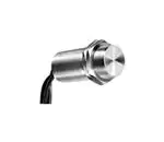
103SR Series Hall-effect position sensors are
completely sealed in threaded aluminum bushings,
and meet NEMA 3, 3R, 3S, 4, 4X, 12 and 13
requirements.
PK 88782
Output can be directly connected to most
electronic circuitry such as microprocessors,
integrated logic, discrete transistors and SCRs with
compatible voltage specifications.
ABSOLUTE MAXIMUM RATINGS*
Parameters
4.5 VDC to 5.5 VDC
6 VDC to 24 VDC
4.5 VDC to 24 VDC
Supply Voltage (Vs)**
Voltage Externally
Applied to Output
Output Current
Temperature
Operate & Storage
-1.2 VDC to +10 VDC
+10 VDC max. (OFF only)
-0.5 VDC min. (ON or OFF)
20 mA max.
-1.2 VDC to +24 VDC
+20 VDC max. (OFF only)
-0.5 VDC min. (ON or OFF)
40 mA max.
-1.0 VDC to +25 VDC
+25 VDC max. (OFF only)
-0.5 VDC min. (ON or OFF)
20 mA max.
-40°C to +100°C
-40°C to +100°C
-40°C to +100°C
(-40°F to +212°F)
(-40°F to +212°F)
(-40°F to +212°F)
* Absolute maximum ratings are the extreme limits that the device will withstand without damage to the device.
However, the electrical and magnetic characteristics are not guaranteed as the maximum limits (above recommended
operating conditions) are approached, nor will the device necessarily operate at absolute maximum rating.
** Vs is the unregulated supply voltage.
TABLE 1 LEADWIRE LENGTH
Catalog Listing
103SR11A-1
103SR11A-2
103SR11A-3
103SR12A-1
103SR12A-2
103SR12A-3
103SR12A-4
103SR12A-7
103SR12S-2
103SR13A-1
103SR13A-2
103SR13A-4
103SR13A-6
103SR13A-8
103SR13A-9
103SR13A-10
103SR13A-11
103SR13A-12
103SR13A-13
103SR13A-14
103SR13A-16
103SR14A-1
103SR14A-2
103SR17A-1
103SR17A-2
103SR18-1
Description
152,4 mm (6 in.), Type 1
1 meter (39.37 in.), Type 2
203,2 mm (8.0 in.), Type 1
152,4 mm (6 in.), Type 1
1 meter (39.37 in.), Type 2
1,52 meters (60 in.), Type 1
304,8 mm (12 in.), Type 1
3,66 meters (12 ft.), Type 2
1 meter (39.37 in.), Type 2
152,4 mm (6 in.), Type 1
1 meter (39.37 in.), Type 2
1 meter (39.37 in.), Type 1
3,05 meters (120 in.), Type 1
1 meter (39.37 in.), Type 2 w/SST
bushing
3 meters (118 in.), Type 3
142,24 mm (5.60 in.), Type 2
1 meter (39.37 in.), Type 3
2005,58 mm (78.96 in.), Type 2
152,4 mm (6 in.), Type 1
304,8 mm (12 in.), Type 1
355,6 mm (14 in.), Type 1
152,4 mm (6 in.), Type 1
1 meter (39.37 in.), Type 2
152,4 mm (6 in.), Type 1
1 meter (39.37 in.), Type 2
99,1 mm (3.9 in.), Type 4
Sensing and Control
TABLE 2 LEADWIRE TYPE
Type
Description
Type 1
24 gage stranded, irradated Polyethylene
insulated
Type 2
22 gage PVC insulated conductor with black
molded PVC jacket
Type 3
22 gage insulated conductors with yellow
thermoplastic polyurethane jacket
Type 4
24 gage irradiated polyethylene
CAUTION
PRODUCT DAMAGE
•
Do not reverse supply voltage polarity
•
Do not exceed maximum ratings
Failure to comply with these instructions may result
in product damage.
�103SR Series
PK 88782
ELECTRICAL AND MAGNETIC SPECIFICATIONS
Refer to Table 1 (Page 1) for leadwire lengths available to individual catalog listings, then order accordingly.
Refer to Table 2 (Page 1) for explanation of different leadwire types.
103SR11A-x
103SR12A-x
103SR13A-x
103SR14A-x
103SR17A-x
103SR18-x
Listing
Supply
4.5 VDC 6 VDC 4.5 VDC 4.5 VDC 4.5 VDC 4.5 VDC Voltage
5.5 VDC
24 VDC
24 VDC
24 VDC
24 VDC
24 VDC
Supply
4 mA max.
10 mA max.
10 mA max.
10 mA max.
10 mA max.
10 mA
Current
max.
Output
Source
Source
Sink
Sink
Sink
Sink
Type
(PNP)
(PNP)
(NPN)
(NPN)
(NPN)
(NPN)
Output
(Vs - 1.5) V
(Vs - 1.5) V
0.4 V max.
0.4 V max.
0.4 V max.
0.4 V max.
Voltage
max.
max.
Output
20 mA max.
20 mA max.
20 mA max.
20 mA max.
20 mA max.
20 mA
Current
max.
Magnetic Gauss*
Type
Unipolar
Unipolar
Unipolar
Unipolar
Bipolar
Latching
0° C to 70° C Temperature Range
Max. Op
735
495
475
—
180
90
Min. Rel.
25
120
135
—
-180
-90
Min. Dif.
50
40
40
—
40
40
-40° C to 100°C Temperature Range
Max. Op.
—
—
495
160
205
120
Min. Rel.
—
—
200
5
-205
-120
Min. Dif.
—
—
35
8
35
40
+25°C Typ.
Typ. Op.
350
350
400
90
50
50
Typ. Rel.
215
245
250
45
-50
-50
Typ. Dif.
135
85
85
45
100
80
* Unipolar: sensor has plus maximum operate point, plus minimum release point. One magnetic pole (south) is
required to operate and release a unipolar sensor.
Bipolar sensor has plus (south pole) operate point and minus (north pole) minimum release point. Operate and
release points can be both positive or both negative. Latching cannot be guaranteed. Ring magnets are usually
used with bipolar sensors.
Bipolar latching sensor is guaranteed to switch on with plus (south pole) gauss only, and switch off with negative
(north pole) gauss only.
2 Honeywell • Sensing and Control
For application help: call 1-800-537-6945
�103SR Series
PK 88782
INTERFACING SENSING AND CONTROL HALL EFFECT SENSORS
The schematics shown are typical of the outputs
with which Sensing and Control Hall effect sensors
can be interfaced. Values shown are representative
only.
CURRENT SINKING OUTPUTS
(Current flows through load into sensor.) Output
terminal is open collector. In the unoperated
condition (IL = 0), the output voltage is normally
high.
For application help: call 1-800-537-6945
CURRENT SOURCING OUTPUTS
(Current flows from sensor through load.) Output
terminal is open emitter. In the unoperated condition
(IL = 0), the output voltage is normally low.
Honeywell • Sensing and Control 3
�103SR Series
PK 88782
TROUBLESHOOTING
If sensor does not operate, follow these steps:
1. Assure wiring is correct. Load must be connected.
2. Measure supply voltage across Red (+) and Black
(-) leads to verify presence of proper voltage.
3. Connect positive voltmeter lead to Green (output)
lead, and negative voltmeter lead to Black
(ground). With magnet removed (or north pole
present), reading should be:
Catalog Listing
103SR11A-1
103SR12A-1
103SR13A-1
103SR14A-1
103SR17A-1*
Voltage Reading
0
0
Vs
Vs
Vs
When magnet (south pole) moves toward sensor
face (beyond operating point), output should change
state and read:
Catalog Listing
Voltage Reading
103SR11A-1
3.4 V min.
103SR12A-1
(Vs - 2)V min.
103SR13A-1
0.4 V max.
103SR14A-1
0.4 V max.
103SR17A-1*
0.4 V max.
*North magnetic pole must be present to ensure
device is OFF due to bipolar magnetic operation.
MOUNTING DIMENSIONS
(for reference only)
WARRANTY/REMEDY
Honeywell warrants goods of its manufacture as
being free of defective materials and faulty
workmanship. Contact your local sales office for
warranty information. If warranted goods are
returned to Honeywell during the period of coverage,
Honeywell will repair or replace without charge those
items it finds defective. The foregoing is Buyer’s sole
remedy and is in lieu of all other warranties,
expressed or implied, including those of
merchantability and fitness for a particular
purpose.
Specifications may change without notice. The
information we supply is believed to be accurate and
reliable as of this printing. However, we assume no
responsibility for its use.While we provide application
assistance personally, through our literature and the
Honeywell web site, it is up to the customer to
determine the suitability of the product in the
application.
For application assistance, current specifications, or
name of the nearest Authorized Distributor, contact a
nearby sales office. Or call:
1-800-537-6945 USA
1-800-737-3360 Canada
1-815-235-6847 International
FAX
1-815-235-6545 USA
INTERNET
www.honeywell.com/sensing
info.sc@honeywell.com
LEADWIRE COLOR CODE
Color
Stranded
Red
Black
Green
Cable
Red
Black
White (Type 2)
Brown (Type 3)
Sensing and Control
Honeywell Inc.
11 West Spring Street
Freeport, Illinois 61032
Printed with Soy Ink
on 50% Recycled Paper
PK 88782-3-EN IL50 GLO 0303 Printed in USA
www.honeywell.com/sensing
Description
Vs (+)
Ground (-)
Output
Vs (+)
Ground (-)
Output (digital)
Output (linear)
�