ISSUE 3
Installation Instructions for the
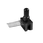
24PC Series Pressure Sensors
WARNING
PERSONAL INJURY
DO NOT USE these products as safety
or emergency stop devices, or in any
other application where failure of the
product could result in personal injury.
Failure to comply with these
instructions could result in death or
serious injury.
GENERAL INFORMATION
24PC Series pressure sensors are four
active element piezoresistive bridges.
When pressure is applied, the resistance
changes and the 24PC provides an
output signal proportional to the input
pressure.
Gage pressure is measured with
respect to ambient pressure. When
applied pressure increases, the
differential voltage V2 - V4 increases. As
pressure decreases, differential voltage
V2 - V4 decreases.
Differential sensors provide a
differential voltage proportional to the
pressure differential between port P2 and
P1. As DP = P2 – P1 increases,
differential voltage V2 - V4 increases. As
DP = P2 – P1 decreases, differential
voltage V2 - V4 decreases.
Absolute sensors measure pressure
with respect to a vacuum reference. As
absolute pressure increases, the
differential voltage V2 - V4 goes more
negative.
SOLDERING
Limit soldering to 315 °C [600 °F]
maximum, with duration of 10 seconds
maximum.
CLEANING
Proper cleaning fluids should be selected,
based on the type of contaminants to be
removed. Honeywell recommends
alcohols or fluorinated solvents. Do not
immerse the sensor.
Automation and Control Products
PK 80082
24PC SERIES PERFORMANCE CHARACTERISTICS
at 10.0 ± 0.01 Vdc Excitation, 25 °C
Min.
Excitation
—
Response Time
—
Input Resistance*
4.0 k
Output Resistance*
4.0 k
Weight
* Measured using a 1 mA current
Typ.
Max.
Units
10
—
5.0 k
5.0 k
2
12
1.0
6.0 k
6.0 k
Vdc
ms
Ohm
Ohm
gram
ENVIRONMENTAL SPECIFICATIONS
Operating
Temperature
Storage
Temperature
Shock
Vibration
-40 °C to 85 °C [-40 °F to 185 °F]
-55 °C to 100 °C [-67 °F to 212 °F]
Qualification tested to 150 G
Qualification tested: 0 kHz to 2 kHz, 20 G sine
Note: For media compatibility specifications, refer to catalog or
web site: www.honeywell.com/sensing
24PC CIRCUIT TERMINATION
1
+
VS
2
+V -
-
O
4
3
Pin 1 = Vs (+)
Pin 2 = Output + (V2)
Pin 4 = Output (-)
Pin 3 = Ground - (V4)
Pin 1 is notched
Pin 2 is next to Pin 1, etc.
CONSTANT CURRENT EXCITATION SCHEMATIC
Constant
Current
Source
R1
+
Output Voltage
R4
R2
R5
Shunt Resistor for
High Temperture
Corrections
R3
-
Noncompensated pressure sensors, excited by
constant current instead of voltage, exhibit temperature
compensation of span.
Constant current excitation has an additional benefit of
temperature measurement. When driven by a constant
current source, a silicon pressure sensor’s terminal
voltage will rise with increased temperature. The rise in
voltage not only compensates for the span, but is also
an indication of sensor temperature.
Honeywell 2002, All Rights Reserved
�24PC Series Pressure Sensors
ISSUE 3
PK 80082
24PCLASER BRANDING SCHEME (Note: Alternate form is entire catalog listing)
4
B
F
6
G
CATALOG
LISTING
STAMP
XX
XX
G
6
F
B
4
2002
DATE STAMP
CODE
= Special (Sequentially numbered)
= Pressure measurement: G = Gage, D = Differential,
A = Absolute
= Termination style: 2 = 2 x 2, 5 = Wire Harness,
or 6 = 1 x 4
= Media seal: F = Fluorosilicone, E = EPDM, N = Neoprene,
S = Silicone, V = Viton
= Range (psi): A = 1, B = 5, C = 15, D = 30, E = 0.5,
F = 100, G = 250
= Type: (4 = Uncompensated)
10 (Note: Alternate date code is 102002)
10
= Week in the year
2002 = Year
ADDITIONAL PORT VARIATIONS (dimensions for reference only) mm/in
B Barbed
J Needle
C Luer
D Modular
K Reverse 90° Port
H M5 Thread*
M ¼-28 Thread**
I 90° Port
S Manifold
* Recommended torque for sealing is 4 in-lb. Do not exceed 6 in-lb of torque. Use size 007 O-Ring. O-Ring
counterbore dimensions are 0.04 ± .005 in D x 0.300 ± .003 in Dia.
** Recommended torque for sealing is 8 in-lb. Do not exceed 12 in-lb. Use size 009 O-Ring. O-Ring Counterbore
dimensions are .040 ± .002 in D x 0.360 ± .003 in Dia.
2 Honeywell • Automation and Control Products
�24PC Series Pressure Sensors
ISSUE 3
PK 80082
ADDITIONAL PORT VARIATIONS (dimensions for reference only) mm/in
G SMALL FLOW THROUGH
U LARGE FLOW THROUGH
MOUNTING DIMENSIONS (dimensions for reference only) mm/in
GAGE SENSORS
1 x 4 Termination (Style 6) Port Style A, Straight
Pin 1 is notched, Pin 2 is next to Pin 1, etc.
2 x 2 Termination (Style 2) Port Style A, Straight
Pin 1 is notched, Pin 1 is shown at lower right corner.
Pins 2, 3, 4 are clockwise.
Honeywell • Automation and Control Products 3
�24PC Series Pressure Sensors
ISSUE 3
PK 80082
MOUNTING DIMENSIONS (dimensions for reference only) mm/in
DIFFERENTIAL SENSOR 1 X 4 Termination (Style 6)
ACCESSORY
Port Style A, Straight (Only)
PC-10182 — Steel Lockring
WARRANTY/REMEDY
Honeywell warrants goods of its manufacture as being
free of defective materials and faulty workmanship.
Contact your local sales office for warranty information. If
warranted goods are returned to Honeywell during the
period of coverage, Honeywell will repair or replace
without charge those items it finds defective. The
foregoing is Buyer’s sole remedy and is in lieu of all
other warranties, expressed or implied, including
those of merchantability and fitness for a particular
purpose.
Specifications may change without notice. The
information we supply is believed to be accurate and
reliable as of this printing. However, we assume no
responsibility for its use.
Automation and Control Products
Honeywell Inc.
11 West Spring Street
Freeport, Illinois 61032
PK 80082-3-EN IL50 GLO 0902 Printed in USA
While we provide application assistance personally,
through our literature and the Honeywell web site, it is up
to the customer to determine the suitability of the product
in the application.
For application assistance, current specifications, or
name of the nearest Authorized Distributor, contact a
nearby sales office. Or call:
1-800-537-6945 USA
1-800-737-3360 Canada
1-815-235-6847 International
FAX
1-815-235-6545 USA
INTERNET
www.honeywell.com/sensing
info.sc@honeywell.com
www.honeywell.com/sensing
�