Interactive Catalog Supplements Catalog PDFs
If you need detailed product information, or help choosing the right
product for your application, see our Interactive Catalog. Use the
Interactive Catalog to access the most complete and up-to-date
information available.
The Interactive Catalog provides an extensive collection of product
specifications, application data, and technical literature that can be
searched based on criteria you select.
Sensing and Control
Interactive
Catalog...
Click this icon to try
the Interactive Catalog.
This PDF catalog information was published in November 2000.
Sensing and Control
Honeywell Inc.
11 West Spring Street
Freeport, IL 61032
www.honeywell.com/sensing
�Limit and Enclosed Switches
Momentary Cable Pull Limit Switches: For Signaling Applications
When using direct acting contacts, Momentary Cable Pull Limit Switches provide a means to
manually force disconnection of a normally closed control circuit by pulling on an attached
cable. Momentary switches cause contact transfer if the cable is manually pulled and held.
When the cable is released, switch contacts return to their original state. Momentary
switches have either direct-acting contacts or snap-action contacts.
Cable length may be up to 200 ft. in a straight line for Single Head switches, and up to 400 ft.
(200 ft. in each direction) for Duplex Head switches.
FEATURES
1 Offered in Single Head and Duplex
Head versions
1 Optional direct acting contacts enhance
reliability
1 Duplex Head switches cover up to 400
ft. cable spans (200 ft. in each direction)
1 Single Head switches have one normally
open auxiliary contact, while Duplex
Head switches have up to three
normally open and two normally closed
auxiliary contacts
1 Four conduit opening thread size
options: 1/2-14 NPT, 20mm, PF1/2 and
PG13.5
1 Compact size of Single Head switches
fits into tight spaces
1 Sealed to NEMA 1, 3, 4 and 13
1 Smart Distributed System output
available on Duplex version for
monitoring only
1 UL listed
1 CSA certified
1 CE certified
1 Temperature range: –1° to 70°C (30° to
158°F)
1 Available with indicators
1 Duplex versions available with high
visibility pilot light
TYPICAL APPLICATIONS
TYPICAL DUPLEX HEAD SWITCH INSTALLATION
1
1
1
1
1
Conveyors
Packaging machinery
Assembly lines
Process equipment
Transfer lines
Honeywell 1 Sensing and Control 1 1-800-537-6945 USA 1 F1-815-235-6847 International 1 1-800-737-3360 Canada
A65
Limit/Enclosed
MOMENTARY (CONTACT SWITCH) OPERATING HEAD
Momentary CLS Series Cable Pull Limit Switches are designed for signaling applications;
they are not to be used as emergency stop devices. (For emergency stop applications, see
the Maintained Cable Pull Limit Switches in the Safety Products catalog.)
CLS Series
�Limit and Enclosed Switches
Momentary Cable Pull Limit Switches: For Signaling Applications
CLS Series
TECHNICAL DATA CLS SERIES SPECIFICATIONS
Electrical
Rate thermal current
Ith = 10 A
Rate insulation voltage
Ui = 660 VAC/660 VDC
Impulse voltage
Uimp = 2.5 kV
Contact resistance
< 25 milliohms
Operating rating
AC15
DC13
UL/CSA
U = 600 V: I = 1.2 A
U = 240 V: I = 3 A
U = 120 V: I = 6 A
U = 250 V: I = 0.27 A
U = 24 V: I = 2.8 A
A600/Q300
Mechanical
Protection class
Mechanical life
Temperature Range
Terminal identification
Head/housing material
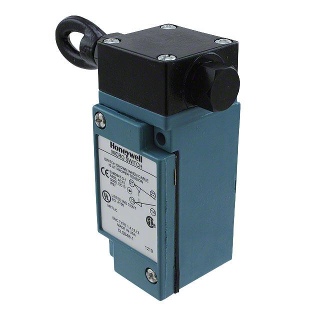
CABLE PULL SWITCH
CHARACTERISTICS
Momentary Cable Pull Limit Switches are
offered with a black operating head and a
blue body. There is a choice of four different
conduit openings: 1/2-14 NPT, 20mm, PF
1/2, and PG13.5. Duplex switches have 3
standard conduit openings with two conduit
plugs provided.
All switches come with a 1NO auxiliary contact as standard.
NEMA 1, 3, 4 and 13
105 operations maximum
–1° to 70°C (30° to 158°F)
Numbering to EN50013
Zinc die cast
An additional auxiliary switch is also available in the Duplex. This auxiliary switch may
be configured as 1NO - 1NC direct acting,
2NO - 2NC snap action (monitoring only) or
1NO - 1NC with Smart Distributed System
output (monitoring only).
Neon and LED indicators are available. A
6 watt incandescent pilot light is available
on the Duplex for high visibility at long
distances.
SMART DISTRIBUTED SYSTEM OUTPUT
VERSION
The Smart Distributed System Output Version provides Smart Distributed System
compatible switch status messaging. The
primary contact block (NC) must be wired to
the control current. The auxiliary contact
block has been replaced with the Smart
Distributed System circuitry.
Snap action contact blocks and the Smart
Distributed Output Version should be used
for monitoring only. These types of switches
should not be used in control circuits.
A66
Honeywell 1 Sensing and Control 1 1-800-537-6945 USA 1 F1-815-235-6847 International 1 1-800-737-3360 Canada
�Limit and Enclosed Switches
Momentary Cable Pull Limit Switches: For Signaling Applications
CLS Series
SINGLE HEAD CLS ORDER GUIDE
CLS
–
MODIFICATION CODES
1 HEAD ASSEMBLED WITH ACTUATOR TO THE LEFT
2 HEAD ASSEMBLED WITH ACTUATOR TO THE FRONT
3 HEAD ASSEMBLED WITH ACTUATOR TO THE
MOUNTING SURFACE
BASIC SWITCH CODE
3 1NO-1NC SNAP ACTION (Monitoring Only)
4 1NO-1NC DIRECT ACTING
5 1NO-1NC DIRECT ACTING 240V NEON INDICATOR
6 1NO-1NC DIRECT ACTING 120V NEON INDICATOR
7 1NO-1NC DIRECT ACTING 24V LED INDICATOR
HEAD CODES
B MOMENTARY
Limit/Enclosed
BODY CODE
A BLUE BODY – PG13.5
B BLUE BODY – 1/2 NPT
C BLUE BODY – 20MM
D BLUE BODY – PF1/2
Notes:
1 Leave the MODIFICATION CODE blank if a modification is not required.
1 Standard head orientation is with actuator to the right.
1 Unit may be field modified.
EXAMPLE CATALOG LISTING
Catalog Listing
Description
CLSD4B-1
Single Head Cable Pull Limit Switch, Blue Body – PF 1/2, 1NO - 1NC
Direct Acting, Momentary, Head assembled with actuator to the left
DUPLEX HEAD 2CLS ORDER GUIDE
2CLS
BODY CODE
A BLUE BODY – PG13.5
B BLUE BODY – 1/2 NPT
C BLUE BODY – 20MM
D BLUE BODY – PF1/2
PRIMARY BASIC SWITCH CODE – LEFT
1 1NO – 1NC DIRECT ACTING
OPERATING HEAD
B MOMENTARY, BOTH SIDES
–
MODIFICATION CODES
(See chart below for numbered
modification codes.)
INDICATOR – PILOT LIGHT CODE
A 120V – 6W RED PILOT LIGHT
B 120V NEON INDICATOR
C 240V NEON INDICATOR
D 24V LED INDICATOR
AUXILIARY BASIC SWITCH CODE – RIGHT
1 1NO – 1NC DIRECT ACTING
3 2NO – 2NC (DPDT) SNAP ACTION (Monitoring Only)
4 1NO – 1NC WITH SDS OUTPUT (Monitoring Only)
9 NO SWITCH
Notes:
1 No numbered modification code indicates both heads oriented to side (Duplex Head).
1 Standard Conduit openings are left, center, and right with two conduit plugs furnished.
1 Leave the INDICATOR – PILOT LIGHT CODE blank if a pilot light is not required.
1 Leave the HEAD ORIENTATION NUMBERED MODIFICATION CODE blank if not required. Do not enter zero.
EXAMPLE CATALOG LISTING
HEAD ORIENTATION
NUMBERED MOD CODES
MOD CODE
LEFT HEAD RIGHT HEAD
1
FRONT
FRONT
2
FRONT
REAR
Catalog Listing
Description
3
FRONT
SIDE
2CLSB1B1-3
Duplex Head Cable Limit Switch, Blue Body – 1/2 NPT, 1NO – 1NC
Direct Acting, Momentary – Both Sides, 1NO – 1NC Direct Acting, No
Pilot Light, Left Head Front – Right Head Side
4
REAR
FRONT
5
REAR
REAR
6
REAR
SIDE
7
SIDE
FRONT
8
SIDE
REAR
Honeywell 1 Sensing and Control 1 1-800-537-6945 USA 1 F1-815-235-6847 International 1 1-800-737-3360 Canada
A67
�Limit and Enclosed Switches
Momentary Cable Pull Limit Switches: For Signaling Applications
CLS Series
MOUNTING DIMENSIONS
(For reference only)
A68
Honeywell 1 Sensing and Control 1 1-800-537-6945 USA 1 F1-815-235-6847 International 1 1-800-737-3360 Canada
�Limit and Enclosed Switches
Momentary Cable Pull Limit Switches: For Signaling Applications
CLS Series
INSTALLATION HARDWARE
1 Aircraft cable precut to 25, 50, 100, 150
and 200 feet lengths
1 Lockout attachment
1 End springs for long cable spans to
compensate for temperature variations
1 Installation hardware kit supports cable
installations of 25 ft. and 50 ft.
Limit/Enclosed
INSTALLATION HARDWARE ORDER GUIDE
Catalog Listings
Description
CLSZC1
25 ft. Red Aircraft Cable, finished cable dia. 0.187 in
CLSZC2
50 ft. Red Aircraft Cable, finished cable dia. 0.187 in
CLSZC3
100 ft. Red Aircraft Cable, finished cable dia. 0.187 in
CLSZC4
150 ft. Red Aircraft Cable, finished cable dia. 0.187 in
CLSZC5
200 ft. Red Aircraft Cable, finished cable dia. 0.187 in
CLSZ1S
End Spring
CLSZ00
Installation Kit includes: 4 thimbles, 8 wire rope clamps, 1 turnbuckle (w/lock nuts), 9 eyebolts (w/hardware),
1 endspring, 1 conduit fitting
Notes:
1. Eyebolts should be spaced 1.8 to 2.4 m (6 to 8 ft.) apart.
2. One used for each 7.5 m (25 ft.) of cable span.
Honeywell 1 Sensing and Control 1 1-800-537-6945 USA 1 F1-815-235-6847 International 1 1-800-737-3360 Canada
A69
�