FSS-SMT Series
Low Profile Force Sensor
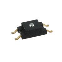
DESCRIPTION
Honeywell’s FSS-SMT Series force sensors are designed to be
one of the most reliable force sensors available as illustrated
by 20 million Mean Cycles To Failure (MCTF) at 25 °C [77 °F]
rating. This low profile Surface Mount Technology (SMT)
sensor allows for automated assembly on a printed circuit
board, often helping the customer to reduce assembly costs.
The FSS-SMT Series force sensor is designed to provide
precise and reliable force sensing performance in a compact
commercial-grade package. The sensor incorporates
Honeywell sensing technology that uses a specialized
piezoresistive micromachined silicon sensing element. The low
power, unamplified, uncompensated Wheatstone bridge circuit
design provides inherently stable millivolt output over the force
range.
Force sensors operate on the principle that the resistance of
silicon-implanted piezoresistors will change when the resistors
flex under applied force. The sensor concentrates force from
the applications, through the stainless steel ball, directly to the
silicon-sensing element. The amount of resistance changes in
proportion to the amount of force being applied. This change in
circuit resistance results in a corresponding mV output level
change.
The sensor package design incorporates patented modular
construction. The use of innovative elastomeric technology and
engineered molded plastics results in load excitation capacities
of 44 N over-force. The stainless steel ball provides excellent
mechanical stability, and is suitable for a variety of potential
medical and commercial applications.
FEATURES/BENEFITS
Surface Mount Technology allows for automated assembly and may eliminate hand soldering
RoHS-compliant materials meet Directive 2002/95/EC
Low deflection (30 microns typical at full scale) help reduce measurement error
Direct mechanical coupling of the actuation ball to the sense element reduces coupling errors and keeps mechanical hysteresis
to a minimum
• Product rating of 20 million MCTF at 25 °C [77 °F], subject to application variation, provides for consistent output over time and
reduces repairs or replacements
• Small size minimizes space on the printed circuit board (PCB)
• Provides enhanced sensitivity without compromising signal integrity, resulting in low system noise and reducing measurement
errors
• Electrically ratiometric output accommodates supply voltage variations, leading to low ratiometricity error
• Low voltage supply allows for use in many battery powered applications
• High resistance to electrostatic discharge (ESD) (8 KV) meets ESD Sensitivity Classification Level 3, reducing special handling
during assembly
• Sensor output has low sensitivity to many mounting stresses
•
•
•
•
�FSS-SMT Series
POTENTIAL APPLICATIONS
Medical
• Infusion pumps
• Ambulatory non-invasive pumps
• Occlusion detection
• Kidney dialysis machines
• Enteral pumps
Table 1. Absolute Maximum Ratings
Parameter
Electro-Static Discharge (ESD)
2
Storage temperature
3
Solderability
Commercial
• Load and compression sensing
• Variable tension control
• Wire bonding equipment
1
Min.
-40 [-40]
-
Max.
8
100 [212]
260 [500] for 10 s
Unit
kV
°C [°F]
°C [°F]
Table 2. Operating Specifications (Performance characteristics at 5.0 ± 0.01 Vdc excitation, 25 °C [77 °F])
Parameter
4
Supply voltage
Operating force
5
Operating temperature
6
Offset
7
Span
8
Sensitivity
9
Force non-linearity (BFSL)
10
Repeatability at 2.9 N
11
Mechanical hysteresis
12
Thermal effect on offset
25 °C to 0 °C [77 °F to 32 °F],
25 °C to 50 °C [77 °F to 122 °F]
13
Thermal effect on span
25 °C to 0 °C [77 °F to 32 °F],
25 °C to 50 °C [77 °F to 122 °F]
Input resistance
Output resistance
14
Over force
2
www.honeywell.com/sensing
Min.
3.0
0
-40 [-40]
-15
150
10.2
-
Typical
5.0
0
180
12.2
±0.7
±1.5
±0.5
Max.
6.0
14.7
85 [185]
15
210
14.3
±1.5
-
Unit
V
N
°C [°F]
mV
mV
mV/N
%FSS
mV
%FSS
-
±0.5
-
mV
-
±5.5
-
%FSS
4.0
4.0
44
5.0
5.0
-
6.0
6.0
-
kOhm
kOhm
N
�Low Profile Force Sensor
Table 3. Environmental Specifications
Parameter
Shock
Vibration
15
Mean Cycles To Failure (MCTF)
Characteristics
Qualification tested to 150 G
Qualification tested to 0 to 2 kHz, 20 G sine
20 million at 25 ° C [77 ° F]
Notes:
1. Absolute maximum ratings are the extreme limits that the device can withstand without damage to the device.
2. The temperature range over which the product may safely be exposed without excitation or force applied. Under these
conditions the product will remain in specification after excursion to any temperatures in this range. Exposure to temperatures
beyond this range may cause permanent damage to the product.
3. The maximum temperature and time for which the product can be exposed to for processing of solder electrical connections.
4. The range of voltage excitation which can be supplied to the product to produce an output which is proportional to Force but
due to Ratiometricity errors may not remain within the specified performance limits.
5. The temperature range over which the product will produce an output proportional to force but may not remain within the
specified performance limits.
6. The output signal obtained when the zero force is applied to the sensor. Also known as "null" or "zero".
7. The algebraic difference between output signal measured at the upper and lower limits of the Operating Force Range. Also
known as "full scale output" or simply "span".
8. The ratio of output signal change to the corresponding input force change. Sensitivity is determined by computing the ratio of
Span to the specified Operating Force Range.
9. Force Non-Linearity (Best Fit Straight Line): The maximum deviation of product output from a straight line fitted to output
measured over the operating force range. The straight line through a set of points which minimizes the sum of the square of
the deviations of each of the points from the straight line.
10. The maximum difference between output readings when the same force is applied consecutively, under the same operating
conditions, with force approaching from the same direction within the operating force range.
11. The maximum difference between output readings when the same force is applied consecutively, under the same operating
conditions, with force approaching from opposite directions within the operating force range.
12. The maximum deviation in Offset due to changes in temperature over the Operating Temperature Range, relative to Offset
measured at 25 °C.
13. The maximum deviation in Full Scale Span due to changes in temperature over the Operating Temperature Range, relative to
Full Scale Span measured at 25 °C.
14. The maximum force which may safely be applied to the product for it to remain in specification once force is returned to the
Operating Force Range. Exposure to higher forces may cause permanent damage to the product. Unless otherwise specified
this applies to all temperature within the Operating Temperature Range.
15. MCTF is a basic measure of reliability for a non-repairable device. It is the mean number of cycles to maximum operating force
over which a sensor can be expected to operate until failure. The mean value is determined statistically from a probability
distribution for failures based upon test data. MCTF may vary depending on the specific application in which a sensor is
utilized.
Honeywell Sensing and Control
3
�Figure 1. Sensor Pinout
Figure 2. Excitation Schematics – Excitation 5 Vdc Typ.,
6 Vdc max.
FS Series Circuit
1. Circled numbers refer to sensor terminals (pins).
Pin 1 = Supply Vs (+)
Pin 2 = Output Vo (+)
Pin 3 = Ground Vg (-)
Pin 4 = Output Vo (-)
2. The force sensor may be powered by voltage or current. Maximum supply voltage is not to exceed 6 V. Maximum supply
current is not to exceed 1.2 mA. Power is applied across Pin 1 and Pin 3.
3. The sensor output should be measured as a differential voltage across Pin 2 and Pin 4 (Vo=Vo(+)-Vo(-)). The output is
ratiometric to the supply voltage. Shifts in supply voltage will cause shifts in output. Neither Pin 2 nor Pin 4 should be tied to
ground or voltage supply.
Figure 3. Mounting Dimensions (for reference only) in mm
4
www.honeywell.com/sensing
�Low Profile Force Sensor
Figure 4. Suggested Land Pattern in mm
Table 4. Order Guide
Catalog Listing
FSS1500NGT
FSS1500NGR
Packaging*
Tube
Tape and reel (1,000 units)
* Tape and reel packaging in development
Honeywell Sensing and Control
5
�WARNING
WARNING
PERSONAL INJURY
MISUSE OF DOCUMENTATION
DO NOT USE these products as safety or emergency stop
devices or in any other application where failure of the
product could result in personal injury.
Failure to comply with these instructions could result in
death or serious injury.
•
WARRANTY/REMEDY
Honeywell warrants goods of its manufacture as being free of
defective materials and faulty workmanship. Honeywell’s
standard product warranty applies unless agreed to otherwise
by Honeywell in writing; please refer to your order
acknowledgement or consult your local sales office for specific
warranty details. If warranted goods are returned to Honeywell
during the period of coverage, Honeywell will repair or replace,
at its option, without charge those items it finds defective. The
foregoing is buyer’s sole remedy and is in lieu of all other
warranties, expressed or implied, including those of
merchantability and fitness for a particular purpose. In no
event shall Honeywell be liable for consequential, special,
or indirect damages.
The information presented in this product sheet is for
reference only. Do not use this document as a product
installation guide.
• Complete installation, operation, and maintenance
information is provided in the instructions supplied with
each product.
Failure to comply with these instructions could result in
death or serious injury.
SALES AND SERVICE
Honeywell serves its customers through a worldwide network
of sales offices, representatives and distributors. For
application assistance, current specifications, pricing or name
of the nearest Authorized Distributor, contact your local sales
office or:
E-mail: info.sc@honeywell.com
Internet: www.honeywell.com/sensing
Phone and Fax:
While we provide application assistance personally, through
our literature and the Honeywell web site, it is up to the
customer to determine the suitability of the product in the
application.
Specifications may change without notice. The information we
supply is believed to be accurate and reliable as of this
printing. However, we assume no responsibility for its use.
Asia Pacific
+65 6355-2828
+65 6445-3033 Fax
Europe
+44 (0) 1698 481481
+44 (0) 1698 481676 Fax
Latin America +1-305-805-8188
+1-305-883-8257 Fax
USA/Canada +1-800-537-6945
+1-815-235-6847
+1-815-235-6545 Fax
Sensing and Control
Honeywell
1985 Douglas Drive North
Golden Valley, MN 55422
www.honeywell.com
008181-1-EN IL50 GLO Printed in USA
July 2009
© 2009 Honeywell International Inc.
�
很抱歉,暂时无法提供与“FSS1500NGT”相匹配的价格&库存,您可以联系我们找货
免费人工找货- 国内价格
- 25+902.51103
- 50+866.41042
- 100+840.41852


 工商网监
湘ICP备2023018690号
工商网监
湘ICP备2023018690号
