MPR SERIES
32332628
Issue H
MicroPressure Board Mount Pressure Sensors
Compact, High Accuracy, Compensated/Amplified
DESCRIPTION
The MPR Series is a very small
piezoresistive silicon pressure sensor
offering a digital output for reading
pressure over the specified full scale
pressure span and temperature range.
It is calibrated and compensated over a
specific temperature range for sensor
offset, sensitivity, temperature effects,
and non-linearity using an on-board
Application Specific Integrated Circuit
(ASIC). This product is designed to meet
the requirements of higher volume
medical (consumer and non-consumer)
devices, commercial appliance, and
industrial/HVAC applications.
DIFFERENTIATION
• Application-specific design addresses
various application needs and
challenges.
• Digital output: Plug and play feature
enables ease of implementation and
system level connectivity.
• Total Error Band: Provides a more
comprehensive measurement of
performance over the compensated
temperature range, which minimizes
testing and calibrating every
sensor, thereby potentially reducing
manufacturing cost; improves sensor
accuracy and offers ease of sensor
interchangeability due to minimal partto-part variation. (See Figure 1.)
VALUE TO CUSTOMERS
• Very small form factor: Enables
portability by addressing weight, size,
and space restrictions; occupies less
area on the PCB.
• Wide pressure ranges simplify use.
• Enhances performance: Output
accelerates performance through
reduced conversion requirements and
direct interface to microprocessors.
• Value solution: Cost-effective, higher
volume solution with configurable
options.
• Meets IPC/JEDEC J-STD-020D.1
Moisture Sensitivity Level 1
requirements: Allows avoidance of
thermal and mechanical damage
during solder reflow attachment and/
or repair that lesser rated sensors may
incur; allows long floor life when stored
as specified (simplifying storage and
reducing scrap); eliminates lengthy
bakes prior to reflow, and allows for
lean manufacturing due to stability
and usability shortly after reflow.
• Meets food safety certification for
North America, Europe and Asia (see
Table 2).
POTENTIAL APPLICATIONS
• Consumer medical: Non-invasive
blood pressure monitoring, negativepressure wound therapy, breast pumps,
mobile oxygen concentrators, airflow
monitors, CPAP water tanks, and
medical wearables
• Non-consumer medical: Invasive blood
pressure monitors, ambulatory blood
pressure measurement
• Industrial: Air braking systems, gas and
water meters
• Consumer: Coffee machines,
humidifiers, air beds, washing
machines, dishwashers
FEATURES
• 5 mm x 5 mm [0.20 in x 0.20 in]
package footprint
• Calibrated and compensated
• 60 mbar to 2.5 bar | 6 kPa to 250 kPa |
1 psi to 30 psi
• 24-bit digital I2C or SPI-compatible output
• IoT (Internet of Things) ready interface
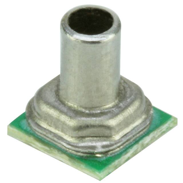
• Stainless steel pressure port
• Compatible with a variety of liquid media
• Absolute and gage pressure types
• Total Error Band after customer autozero: As low as ±1.25 %FSS
• Compensated temperature range: 0ºC to
50ºC [32ºF to 122ºF]
• REACH and RoHS compliant
• Meets IPC/JEDEC J-STD-020D.1
Moisture Sensitivity Level 1
• Select sensors available on breakout
board for easy evaluation and testing
• Ultra-low power consumption (as low
as 0.01 mW typ. average power, 1 Hz
measurement frequency)
• Sensor materials have been tested and
certified for these food safety standards:
- NSF-169
- BPA Free
- LFGB
The MPR Series joins
an extensive line of
board mount pressure
sensors for potential use
in medical, industrial, and
consumer applications. To view
the entire product portfolio,
click here.
�MICROPRESSURE BOARD MOUNT PRESSURE SENSORS, MPR SERIES
Table of Contents
General Specifications. . . . . . . . . . . . . . . . . . . . . . . . . . . . . . . . . . . . . . . . . . . . . . . . . . . . . . . . . . . . . . . . . . . . . . . . . . . . . . . . . . . . . . . . . . . . . . . . . . 3-4
Power Consumption and Standby Mode. . . . . . . . . . . . . . . . . . . . . . . . . . . . . . . . . . . . . . . . . . . . . . . . . . . . . . . . . . . . . . . . . . . . . . . . . . . . . . . . . 5-6
Product Nomenclature and Order Guide. . . . . . . . . . . . . . . . . . . . . . . . . . . . . . . . . . . . . . . . . . . . . . . . . . . . . . . . . . . . . . . . . . . . . . . . . . . . . . . . . . . 7
Pressure Port/Range/Reference Availability . . . . . . . . . . . . . . . . . . . . . . . . . . . . . . . . . . . . . . . . . . . . . . . . . . . . . . . . . . . . . . . . . . . . . . . . . . . . . . 8
Pressure Range Specifications:
60 mbar to 2.5 bar . . . . . . . . . . . . . . . . . . . . . . . . . . . . . . . . . . . . . . . . . . . . . . . . . . . . . . . . . . . . . . . . . . . . . . . . . . . . . . . . . . . . . . . . . . . . . . . . . . . . . . . . . . . . . . . 9
6 kPa to 250 kPa . . . . . . . . . . . . . . . . . . . . . . . . . . . . . . . . . . . . . . . . . . . . . . . . . . . . . . . . . . . . . . . . . . . . . . . . . . . . . . . . . . . . . . . . . . . . . . . . . . . . . . . . . . . . . . . 10
1 psi to 30 psi . . . . . . . . . . . . . . . . . . . . . . . . . . . . . . . . . . . . . . . . . . . . . . . . . . . . . . . . . . . . . . . . . . . . . . . . . . . . . . . . . . . . . . . . . . . . . . . . . . . . . . . . . . . . . . . . . . . 11
0 mmHg to 300 mmHg . . . . . . . . . . . . . . . . . .. . . . . . . . . . . . . . . . . . . . . . . . . . . . . . . . . . . . . . . . . . . . . . . . . . . . . . . . . . . . . . . . . . . . . . . . . . . . . . . . . . . . . . . 11
1.0
GENERAL INFORMATION. . . . . . . . . . . . . . . . . . . . . . . . . . . . . . . . . . . . . . . . . . . . . . . . . . . . . . . . . . . . . . . . . . . . . . . . . . . . . . . . . . . . . . . . . . 12
2.0
PINOUT AND FUNCTIONALITY. . . . . . . . . . . . . . . . . . . . . . . . . . . . . . . . . . . . . . . . . . . . . . . . . . . . . . . . . . . . . . . . . . . . . . . . . . . . . . . . . . . . . 12
3.0
START-UP TIMING. . . . . . . . . . . . . . . . . . .. . . . . . . . . . . . . . . . . . . . . . . . . . . . . . . . . . . . . . . . . . . . . . . . . . . . . . . . . . . . . . . . . . . . . . . . . . . . . . . 12
4.0
POWER SUPPLY REQUIREMENT. . . . . . . . . . . . . . . . . . . . . . . . . . . . . . . . . . . . . . . . . . . . . . . . . . . . . . . . . . . . . . . . . . . . . . . . . . . . . . . . . . 12
5.0
REFERENCE CIRCUIT DESIGN . . . . . . . . . . . . . . . . . . . . . . . . . . . . . . . . . . . . . . . . . . . . . . . . . . . . . . . . . . . . . . . . . . . . . . . . . . . . . . . . . . . . 13
5.1 I2C and SPI Circuit Diagrams . . . . . . . . . . . . . . . . . . . . . . . . . . . . . . . . . . . . . . . . . . . . . . . . . . . . . . . . . . . . . . . . . . . . . . . . . . . . . . . . . . . . . . . . . . . . . . 13
5.2 Bypass Capacitor Use. . . . . . . . . . . . . . . . . . . . . . . . . . . . . . . . . . . . . . . . . . . . . . . . . . . . . . . . . . . . . . . . . . . . . . . . . . . . . . . . . . . . . . . . . . . . . . . . . . . . . . 13
6.0 I2C COMMUNICATIONS
6.1 I2C Bus Configuration . . . . . . . . . . . . . . . . . . . . . . . . . . . . . . . . . . . . . . . . . . . . . . . . . . . . . . . . . . . . . . . . . . . . . . . . . . . . . . . . . . . . . . . . . . . . . . . . . . . . . . 14
6.2 I2C Data Transfer . . . . . . . . . . . . . . . . . . . . . . . . . . . . . . . . . . . . . . . . . . . . . . . . . . . . . . . . . . . . . . . . . . . . . . . . . . . . . . . . . . . . . . . . . . . . . . . . . . . . . . . . . . . 14
6.3 I2C Sensor Address. . . . . . . . . . . . . . . . . . . . . . . . . . . . . . . . . . . . . . . . . . . . . . . . . . . . . . . . . . . . . . . . . . . . . . . . . . . . . . . . . . . . . . . . . . . . . . . . . . . . . . . . . 14
6.4 I2C Pressure Reading. . . . . . . . . . . . . . . . . . . . . . . . . . . . . . . . . . . . . . . . . . . . . . . . . . . . . . . . . . . . . . . . . . . . . . . . . . . . . . . . . . . . . . . . . . . . . . . . . . . . . . . 15
6.5 I2C Status Byte . . . . . . . . . . . . . . . . . . . . . . . . . . . . . . . . . . . . . . . . . . . . . . . . . . . . . . . . . . . . . . . . . . . . . . . . . . . . . . . . . . . . . . . . . . . . . . . . . . . . . . . . . . . . . 15
6.6 I2C Communications. . . . . . . . . . . . . . . . . . . . . . . . . . . . . . . . . . . . . . . . . . . . . . . . . . . . . . . . . . . . . . . . . . . . . . . . . . . . . . . . . . . . . . . . . . . . . . . . . . . . . . . 15
6.6.1 Output Measurement Command. . . . . . . . . . . . . . . . . . . . . . . . . . . . . . . . . . . . . . . . . . . . . . . . . . . . . . . . . . . . . . . . . . . . . . . . . . . . . . . . . . . 15
6.6.2 I2C Sensor Address of 0x18. . . . . . . . . . . . . . . . . . . . . . . . . . . . . . . . . . . . . . . . . . . . . . . . . . . . . . . . . . . . . . . . . . . . . . . . . . . . . . . . . . . . . . . . . 16
6.7 I2C Timing and Level Parameters . . . . . . . . . . . . . . . . . . . . . . . . . . . . . . . . . . . . . . . . . . . . . . . . . . . . . . . . . . . . . . . . . . . . . . . . . . . . . . . . . . . . . . . . . . 16
7.0
SPI COMMUNICATIONS
7.1 SPI Definition . . . . . . . . . . . . . . . . . . . . . . . . . . . . . . . . . . . . . . . . . . . . . . . . . . . . . . . . . . . . . . . . . . . . . . . . . . . . . . . . . . . . . . . . . . . . . . . . . . . . . . . . . . . . . . 17
7.2 SPI Data Transfer. . . . . . . . . . . . . . . . . . . . . . . . . . . . . . . . . . . . . . . . . . . . . . . . . . . . . . . . . . . . . . . . . . . . . . . . . . . . . . . . . . . . . . . . . . . . . . . . . . . . . . . . . . . 17
7.3 SPI Pressure Reading. . . . . . . . . . . . . . . . . . . . . . . . . . . . . . . . . . . . . . . . . . . . . . . . . . . . . . . . . . . . . . . . . . . . . . . . . . . . . . . . . . . . . . . . . . . . . . . . . . . . . . 17
7.4 SPI Status Byte. . . . . . . . . . . . . . . . . . . . . . . . . . . . . . . . . . . . . . . . . . . . . . . . . . . . . . . . . . . . . . . . . . . . . . . . . . . . . . . . . . . . . . . . . . . . . . . . . . . . . . . . . . . . . 18
7.5 SPI Communications . . . . . . . . . . . . . . . . . . . . . . . . . . . . . . . . . . . . . . . . . . . . . . . . . . . . . . . . . . . . . . . . . . . . . . . . . . . . . . . . . . . . . . . . . . . . . . . . . . . . . . 18
7.6 SPI Timing and Level Parameters . . . . . . . . . . . . . . . . . . . . . . . . . . . . . . . . . . . . . . . . . . . . . . . . . . . . . . . . . . . . . . . . . . . . . . . . . . . . . . . . . . . . . . . . . 18
8.0
MPR SERIES DIGITAL OUTPUT PRESSURE CALCULATION. . . . . . . . . . . . . . . . . . . . . . . . . . . . . . . . . . . . . . . . . . . . . . . . . . . . . . . . ��
Long Port Dimensions and Recommended PCB Pad Layout. . . . . . . . . . . . . . . . . . . . . . . . . . . . . . . . . . . . . . . . . . . . . . . . . . . . . . . . . . . . . . . 20
Short Port Dimensions and Recommended PCB Pad Layout. . . . . . . . . . . . . . . . . . . . . . . . . . . . . . . . . . . . . . . . . . . . . . . . . . . . . . . . . . . . . . 21
Tape and Reel Dimensions . . . . . . . . . . . . . . . . . . . . . . . . . . . . . . . . . . . . . . . . . . . . . . . . . . . . . . . . . . . . . . . . . . . . . . . . . . . . . . . . . . . . . . . . . . . . . . . . 22
Reflowable Protective Silicone Cap . . . . . . . . . . . . . . . . . . . . . . . . . . . . . . . . . . . . . . . . . . . . . . . . . . . . . . . . . . . . . . . . . . . . . . . . . . . . . . . . . . . . . . . 23
Reflowable Protective Silicone Cap Removal . . . . . . . . . . . . . . . . . . . . . . . . . . . . . . . . . . . . . . . . . . . . . . . . . . . . . . . . . . . . . . . . . . . . . . . . . . . . . 23
Recommended Tubing. . . . . . . . . . . . . . . . . . . . . . . . . . . . . . . . . . . . . . . . . . . . . . . . . . . . . . . . . . . . . . . . . . . . . . . . . . . . . . . . . . . . . . . . . . . . . . . . . . . . 23
Recommended O-Rings. . . . . . . . . . . . . . . . . . . . . . . . . . . . . . . . . . . . . . . . . . . . . . . . . . . . . . . . . . . . . . . . . . . . . . . . . . . . . . . . . . . . . . . . . . . . . . . . . . . 23
Additional Information. . . . . . . . . . . . . . . . . . . . . . . . . . . . . . . . . . . . . . . . . . . . . . . . . . . . . . . . . . . . . . . . . . . . . . . . . . . . . . . . . . . . . . . . . . . . . . . . . back
2
sensing.honeywell.com
�MICROPRESSURE BOARD MOUNT PRESSURE SENSORS, MPR SERIES
FIGURE 1. TEB COMPONENTS FOR THE MPR SERIES
Total Error Band (TEB) is a single specification that includes
the major sources of sensor error. TEB should not be
confused with accuracy, which is actually a component of
TEB. TEB is the worst error that the sensor could experience.
Sources of Error
Offset
Honeywell uses the TEB specification in its datasheet
because it is the most comprehensive measurement of
a sensor’s true accuracy. Honeywell also provides the
accuracy specification in order to provide a common
comparison with competitors’ literature that does not use
the TEB specification.
Full Scale Span
Pressure Non-Linearity
Many competitors do not use TEB—they simply specify
the accuracy of their device. Their accuracy specification,
however, may exclude certain parameters. On their
datasheet, the errors are listed individually. When combined,
the total error (or what would be TEB) could be significant.
Total
Error
Band
Accuracy
BFSL
Pressure Hysteresis
Pressure Non-Repeatability
Thermal Effect on Offset
Thermal Effect on Span
Thermal Hysteresis
TABLE 1. ABSOLUTE MAXIMUM RATINGS1
CHARACTERISTIC
MIN.
MAX.
UNIT
Supply voltage (Vsupply)
-0.3
3.6
Vdc
Voltage on any pin
-0.3
Vsupply + 0.3
V
—
4
kV
-40 [-40]
85 [185]
°C [°F]
ESD susceptibility (human body model)
Storage temperature
Soldering peak reflow temperature and time
1
15 s max. at 250°C [482°F]
Absolute maximum ratings are the extreme limits the device will withstand without damage.
TABLE 2. ENVIRONMENTAL SPECIFICATIONS
CHARACTERISTIC
PARAMETER
Humidity:
external surfaces
internal surfaces
0 %RH to 95 %RH, non-condensing
0 %RH to 100 %RH, condensing
Vibration
10 g, 10 Hz to 2 kHz
Shock
50 g, 6 ms duration
Solder reflow
J-STD-020-D.1 Moisture Sensitivity Level 1 (unlimited shelf life when stored at
很抱歉,暂时无法提供与“MPRLS02.5BG0000SA”相匹配的价格&库存,您可以联系我们找货
免费人工找货- 国内价格
- 1+148.89466
- 160+147.83462
- 国内价格 香港价格
- 1+159.664671+20.63380
- 160+158.52796160+20.48690