Agilent HLMP-40xx, HLMP-08xx T-1 3/4, 2 mm x 5 mm Rectangular Bicolor LED Lamps
Data Sheet
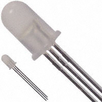
Features • Two color operation • Three leads with one common cathode • Option of straight or spread leads configuration • Diffused, wide visibility range Description The T-1 3/4 HLMP-40xx and 2 mm by 5 mm rectangular HLMP-08xx are three leaded bicolor light sources designed for a variety of applications where dual state illumination is required in the same package. There are two LED chips, mounted on a central common cathode lead for maximum on-axis viewability. Colors between the two chips can be generated by independently pulse width modulating the LED chips.
Selection Guide Package T-1 3/4 Part Number HLMP-4000 HLMP-4000#xxx HLMP-4015 HLMP-0800 HLMP-0805 Color Green/HER Green/Yellow Green/HER Green/Yellow Min. Luminous Intensity Iv (mcd) Green Red Yellow 4.2 2.1 4.2 2.1 20.0 20 2.6 2.1 2.6 1.4 IF (mA) 10 10 20 20 20
Rectangular
�Part Numbering System HLMP - X X X X # X X X Mechanical Options 002: Tape & Reel, Straight Leads 010: Right Angle Housing, Even Leads Color Options 00: High Efficiency Red (HER) / High Efficiency Green 05/15: Yellow / High Efficiency Green Package Options 40: T-1 3/4 (5 mm) 08: Rectangular
Package Dimensions
5.08 (0.200) 4.57 (0.180) 2.23 (0.088) 1.98 (0.078) 5.18 (0.204) 4.93 (0.194)
9.19 (0.362) 8.43 (0.332)
8.00 (0.315) 7.37 (0.290)
25.40 (1.00) MIN. 1.27 (0.050) NOM.
0.89 (0.035) 0.64 (0.025) COMMON CATHODE 0.508 (0.020) SQ. TYP. 2.41 (0.095) 2.03 (0.085) SIDE VIEW 25.40 (1.00) MIN.
5.46 (0.215) 4.98 (0.196) COMMON CATHODE 0.508 (0.020) SQ. TYP. 1.27 (0.050) NOM. 2.54 (0.100) NOM.
1.27 (0.050) NOM.
2.54 (0.100) NOM.
1.27 (0.050) NOM.
GREEN ANODE FLAT INDICATES ANODE RED OR YELLOW ANODE (SHORT LEAD) COMMON CATHODE
6.10 (0.240) 5.59 (0.220) RED OR YELLOW ANODE (SHORT LEAD) COMMON CATHODE GREEN ANODE
HLMP-40xx Straight Leads
HLMP-08xx Straight Leads
Notes: 1. All dimensions are in millimeters (inches). 2. Epoxy meniscus may extend about 1 mm (0.040") down the leads.
2
�Absolute Maximum Ratings at TA = 25˚C Parameter Peak Forward Current Average Forward Current[1,2] (Total) DC Current[2] (Total) Power Dissipation[3] (Total) Operating Temperature Range Storage Temperature Range Reverse Voltage (IR = 100 µA) Transient Forward Current[4] (10 µsec Pulse) Solder Dipping Temperature (1.6 mm (0.063 inch) below seating plane) HER/Green 90 25 30 135 –20 to +100 –55 to +100 5 500 Yellow/Green 60 20 20 135 –20 to +100 –55 to +100 5 500 260 for 5 seconds Units mA mA mA mW ˚C ˚C V mA ˚C
Notes: 1. See Figure 5 to establish pulsed operating conditions. 2. The combined simultaneous current must not exceed the maximum. 3. The combined simultaneous current must not exceed the maximum. 4. The transient peak current is the maximum non-recurring current that can be applied to the device without damaging the LED die and wirebond. It is not recommended that the device be operated at peak currents beyond the peak forward current listed in the Absolute Maximum Ratings.
Electrical/Optical Characteristics at T A = 25˚C Symbol Parameter λPEAK λd τs C VF VR RθJ-PIN 2θ1/2 Peak Wavelength Dominant Wavelength[1] Speed of Response Capacitance Forward Voltage Reverse Voltage Thermal Resistance Included Angle between half luminous intensity points[2] HLMP-40xx HLMP-08xx Luminous Efficacy[3] 5 210 High Efficiency Red Min. Typ. Max. 635 626 90 11 1.9 2.6 5 210 Green Min. Typ. 568 570 260 18 2.2 3.0 2.1 5 210 Max. Yellow Min. Typ. 583 585 90 15 2.6 Max. Units nm nm ns pF V V °C/W VF = 0, f = 1 MHz 20 mA IR = 100 µA Junction-toCathode Lead Test Condition 20 mA 20 mA
65 100 145
65 100 595
65 100 500
degree lm/W
ηV
Notes: 1. The dominant wavelength, λd, is derived from the CIE Chromaticity Diagram and represents the single wavelength which defines the color of the device. 2. θ1/2 is the off-axis angle at which the luminous intensity is half the axial luminous intensity. 3. Radiant intensity, le, in watts steradian, may be found from the equation le = Iv/ηV, where Iv is the luminous intensity in candelas and ηV is the luminous efficacy in lumens/watt.
3
�1.0
EMERALD GREEN HIGH PERFORMANCE GREEN
ORANGE
TA = 25° C
RELATIVE INTENSITY
HIGH EFFICIENCY RED
0.5
YELLOW
0 500
550
600
650
700
750
WAVELENGTH – nm
Figure 1. Relative intensity vs. wavelength.
HIGH EFFICIENCY RED, ORANGE, YELLOW, AND HIGH PERFORMANCE GREEN, EMERALD GREEN 100
RELATIVE LUMINOUS INTENSITY (NORMALIZED AT 20 mA) IF – FORWARD CURRENT – mA
HER, ORANGE, YELLOW, AND HIGH PERFORMANCE GREEN, EMERALD GREEN 1.6 1.4 1.2 1.0 0.8 0.6 0.4 0.2 0 0 5 10 15 20 25 30
80
HIGH PERFORMANCE GREEN, EMERALD GREEN HIGH EFFICIENCY RED/ORANGE YELLOW
60
40
20
0
0
1.0
2.0
3.0
4.0
5.0
VF – FORWARD VOLTAGE – V
IDC – DC CURRENT PER LED – mA
Figure 2. Forward current vs. forward voltage characteristics.
Figure 3. Relative luminous intensity vs. DC forward current.
RATIO OF MAXIMUM TOLERABLE PEAK CURRENT TO MAXIMUM TOLERABLE DC CURRENT IPEAK MAX. IDC MAX.
HER, ORANGE, YELLOW, HIGH PERFORMANCE GREEN, EMERALD GREEN 1.3
ηPEAK – RELATIVE EFFICIENCY (NORMALIZED AT 20 mA)
YELLOW EMERALD GREEN
6 5 4 3 10 KHz 300 Hz 30 KHz 1 KHz 100 KHz 3 KHz 100 Hz
1.2 1.1 1.0 0.9
HIGH PERFORMANCE GREEN HIGH EFFICIENCY RED/ORANGE
0.8 0.7 0.6 0.5 0.4 0 10 20 30 40 50 60 70 80 90
2
1 1.0
10
100
1000
10,000
IPEAK – PEAK SEGMENT CURRENT – mA
tP – PULSE DURATION – µs
Figure 4. Relative efficiency (luminous intensity per unit current) vs. peak LED current.
Figure 5. Maximum tolerable peak current vs. pulse duration. (IDC Max. as per maximum ratings.)
4
�20° 30° 40° 50°
10°
0°
1.0
0.8
0.6 60° 70° 80° 90° 0.4
0.2
10° 20° 30° 40° 50° 60° 70° 80° 90° 100°
Figure 6. Relative luminous intensity vs. angular displacement for HLMP-40xx.
20° 30° 40° 50°
10°
0°
1.0
0.8
0.6 60° 70° 80° 90° 0.4
0.2
10° 20° 30° 40° 50° 60° 70° 80° 90° 100°
Figure 7. Relative luminous intensity vs. angular displacement for HLMP-08xx.
Mechanical Option Matrix Mechanical Option Code 002 010 Definition Tape & Reel, straight leads, minimum increment 1300 pcs/bag Right Angle Housing, even leads, minimum increment 500 pcs/bag
Note: All categories are established for classification of products. Products may not be available in all categories. Please contact your local Agilent representative for further clarification/information.
5
�www.agilent.com/semiconductors
For product information and a complete list of distributors, please go to our web site. For technical assistance call: Americas/Canada: +1 (800) 235-0312 or (916) 788-6763 Europe: +49 (0) 6441 92460 China: 10800 650 0017 Hong Kong: (+65) 6756 2394 India, Australia, New Zealand: (+65) 6755 1939 Japan: (+81 3) 3335-8152 (Domestic/International), or 0120-61-1280 (Domestic Only) Korea: (+65) 6755 1989 Singapore, Malaysia, Vietnam, Thailand, Philippines, Indonesia: (+65) 6755 2044 Taiwan: (+65) 6755 1843 Data subject to change. Copyright © 2003 Agilent Technologies, Inc. Obsoletes 5988-3775EN May 30, 2003 5988-9672EN
�
很抱歉,暂时无法提供与“HLMP-4000”相匹配的价格&库存,您可以联系我们找货
免费人工找货