108-2411
Product
Specification
25 FEB 16 Rev D
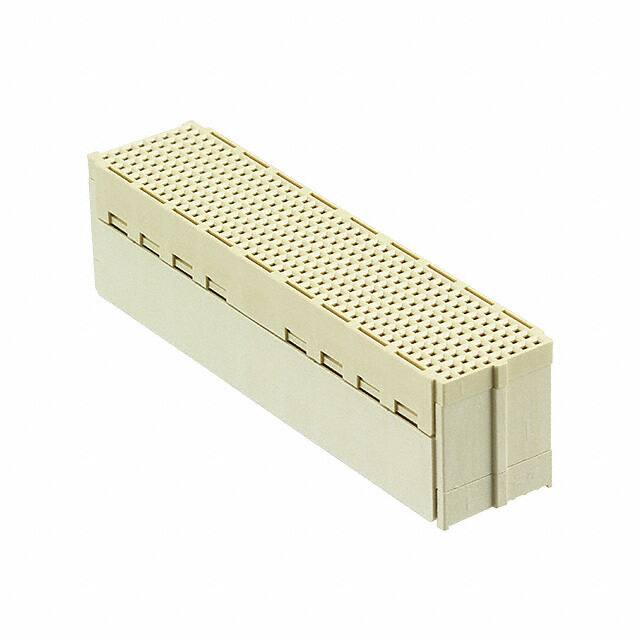
MEZALOK* Stacking Connector System
1.
SCOPE
1.1.
Content
This specification covers performance, tests and quality requirements for the MEZALOK* Stacking
Connector System consisting of a 60 position, 114 position and 320 position pin and socket, Printed
Circuit Board (PCB) surface mount BGA connectors. The product is available in 10, 12, 15 and 18mm
stack heights.
1.2.
Qualification
When tests are performed on the subject product line, procedures specified in Figure 1 shall be used.
All inspections shall be performed using the applicable inspection plan and product drawing.
1.3.
Successful qualification testing for the 60 position and 114 position portion of the product line was
completed on 21Dec10. Additional testing was completed on 25May11, 14Dec12, and 12Feb16. The
Qualification Test Report number for this testing is 501-736.
2.
APPLICABLE DOCUMENTS
The following documents form a part of this specification to the extent specified herein. Unless
otherwise specified, the latest edition of the document applies. In the event of conflict between the
requirements of this specification and the product drawing, the product drawing shall take precedence.
In the event of conflict between the requirements of this specification and the referenced documents,
this specification shall take precedence.
2.1.
TE Connectivity (TE) Documents
●
●
2.2.
114-13279: Application Specification (MEZALOK Stacking PC Board Connectors)
501-736: Qualification Test Report (MEZALOK* Stacking Connector System)
Industry Document
EIA-364: Electrical Connector/Socket Test Procedures Including Environmental Classifications
2.3.
Reference Document
109-197: Test Specification (TE Test Specifications vs EIA and IEC Test Methods)
3.
REQUIREMENTS
3.1.
Design and Construction
Product shall be of the design, construction and physical dimensions specified on the applicable
product drawing.
3.2.
Materials
Materials used in the construction of this product shall be as specified on the applicable product
drawing.
©2016 Tyco Electronics Corporation, a TE Connectivity Ltd. company
All Rights Reserved
| Indicates Change
This controlled document is subject to change.
For latest revision and Regional Customer Service, visit our website at www.te.com
PRODUCT INFORMATION 1-800-522-6752
*Trademark. TE Connectivity, TE connectivity (logo), and TE (logo) are trademarks. Other logos, product and/or company names may be trademarks of their respective owners.
1 of 6
�108-2411
3.3.
Ratings
●
●
●
●
●
3.4.
Voltage: 250 volts AC
Current: 1.5 amperes maximum
Temperature: -55 to 125°C
Characteristic Impedance: 100 ± 5 ohms
Frequency Range: DC to 10+ GHz
Performance and Test Description
Product is designed to meet the electrical, mechanical and environmental performance requirements
specified in Figure 1. Unless otherwise specified, all tests shall be performed at ambient environmental
conditions.
3.5.
Test Requirements and Procedures Summary
Test Description
Requirement
Procedure
Initial examination of product.
Meets requirements of product drawing EIA-364-18.
and Application Specification 114Visual examination and dimensional (C
13279.
of C) inspection per product drawing.
Final examination of product.
Meets visual requirements.
EIA-364-18.
Visual examination.
ELECTRICAL
Low Level Contact Resistance (LLCR).
30 milliohms maximum initial.
∆R 15 milliohms maximum.
EIA-364-23.
Subject specimens to 100 milliamperes
maximum and 20 millivolts maximum
open circuit voltage.
See Figure 3.
Contact resistance, rated current.
30 milliohms maximum initial.
∆R 15 milliohms maximum.
EIA-364-6.
Subject specimens to 1.5 amperes.
See Figure 4.
Insulation resistance.
1000 megohms minimum.
EIA-364-21.
500 volts DC, 2 minute hold.
Test between adjacent contacts of
mated specimens.
Withstanding voltage.
One minute hold with no breakdown or
flashover.
EIA-364-20, Condition I.
750 volts AC at sea level.
Test between adjacent contacts of
mated specimens.
Resistance to soldering heat.
See Note.
EIA-364-56, Procedure 6, Test Level 4.
Subject specimens to 260 +5/-0°C for
10 ± 2 seconds.
Figure 1, continued
Rev D
2 of 6
�108-2411
MECHANICAL
Random vibration
No discontinuities of 1 microsecond or
longer duration.
See Note.
EIA-364-28, with the exception that
frequency and amplitude shall be as
follows:
5 to 100 Hz, PSD increasing at 3
dB/octave;
100 to 1000 Hz, PSD = 0.1 g²/Hz; 1000
to 2000 Hz; PSD decreasing at 6
dB/octave. One hour in each of 3
mutually perpendicular planes.
Mechanical shock.
No discontinuities of 1 microsecond or
longer duration.
See Note.
EIA-364-27, Test Condition G.
Subject mated specimens to 100 Gs
sawtooth shock pulses of 6 milliseconds
duration. Three shocks in each direction
applied along 3 mutually perpendicular
planes, 18 total shocks.
Durability.
See Note.
EIA-364-9.
Mate and unmate specimens for 500
cycles at a maximum rate of 475 cycles
per hour.
Mating force.
136 Gs times the number of contacts
maximum.
320 position: 260 N average
114 position: 139 N average.
60 position: 70 N average.
EIA-364-13, Method A.
Measure force necessary to mate
specimens at a maximum rate of 12.7
mm per minute. Calculate force per
specimen.
Unmating force.
13 Gs times the number of contacts
minimum.
EIA-364-13, Method A.
Measure force necessary to unmate
specimens at a maximum rate of 12.7
mm per minute. Calculate force per
specimen.
ENVIRONMENTAL
Thermal shock.
See Note.
EIA-364-32.
Subject specimens to the specified
number of cycles (see Figure 2)
between -55 and 125°C with 30 minute
dwells at temperature extremes and 1
minute maximum transition between
temperatures.
Humidity/temperature cycling.
See Note.
EIA-364-31, Method III.
Subject specimens to 10 cycles (10
days) between 25 and 65°C at 80 to
100% RH.
Temperature life.
See Note.
EIA-364-17, Method A, Test Condition
5, Test Time Condition C.
Subject mated specimens to 125°C for
500 hours.
Salt spray.
See Note.
EIA-364-26.
Subject mated specimens to a 5% salt
spray for 48 hours.
Figure 1, end
NOTE
Rev D
Shall meet visual requirements, show no physical damage, and meet requirements of additional
tests as specified in the Product Qualification and Requalification Test Sequence shown in Figure 2
3 of 6
�108-2411
3.6.
Product Qualification and Requalification Test Sequence
Test Group (a)
Test or Examination
1
2
3
4
5
Test Sequence (b)
Initial examination of product
1
1
1
LLCR
3,9
2,5
2,5
Contact resistance, rated current
4,10
3,6
3,6
1
Insulation resistance
2,6
Withstanding voltage
3,7
Resistance to soldering heat
2
Random vibration
6
Mechanical shock
7
Durability
5
Mating force
2
Unmating force
11
Thermal shock
4(c)
Humidity/temperature cycling
Final examination of product
4(d)
5
Temperature life
Salt spray
1
4(e)
8
12
Figure 2
7
7
8
3
NOTE
(a)
(b)
(c)
(d)
(e)
Rev D
See paragraph 4.1.A.
Numbers indicate sequence in which tests are performed.
2000 cycles
5 cycles.
Precondition specimens with 10 durability cycles.
4 of 6
�108-2411
4.
QUALITY ASSURANCE PROVISIONS
4.1.
Qualification Testing
A.
Specimen Selection
Specimens shall be prepared in accordance with applicable Instruction Sheets and shall be
selected at random from current production. Test groups 1, 2 and 3 shall consist of a minimum of
4 specimens each. Test groups 4 and 5 shall consist of a minimum of 3 specimens each.
B.
Test Sequence
Qualification inspection shall be verified by testing specimens as specified in Figure 2.
4.2.
Requalification Testing
If changes significantly affecting form, fit or function are made to the product or manufacturing process,
product assurance shall coordinate requalification testing, consisting of all or part of the original testing
sequence as determined by development/product, quality and reliability engineering.
4.3.
Acceptance
Acceptance is based on verification that the product meets the requirements of Figure 1. Failures
attributed to equipment, test setup or operator deficiencies shall not disqualify the product. If product
failure occurs, corrective action shall be taken and specimens resubmitted for qualification. Testing to
confirm corrective action is required before resubmittal.
4.4.
Quality Conformance Inspection
The applicable quality inspection plan shall specify the sampling acceptable quality level to be used.
Dimensional and functional requirements shall be in accordance with the applicable product drawing
and this specification.
Rev D
5 of 6
�108-2411
Figure 3
LLCR Measurement Points
Figure 4
Contact Resistance, Rated Current Measurement Points
Rev D
6 of 6
�