Instruction Sheet
408-- 10021
16 MAR 10 Rev C
ORIGINAL INSTRUCTIONS
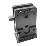
CERTI- CRIMP* II Tool Holder Assembly
1213860- 1 (for Use with the SDE Electric
Bench Terminator)
Crimping Head
CERTI-- CRIMP II Tool
Holder Assembly
1213860-- 1 (for use
with the SDE Electric
Bench Terminator)
SDE Electric
Bench Terminator
Figure 1
1. INTRODUCTION
The CERTI--CRIMP II Tool Holder Assembly
1213860--1 is used to adapt the crimping head from a
CERTI--CRIMP II Hand Tool to an SDE Electric
Bench Terminator. Figure 1 shows a typical crimping
head, mounted to CERTI--CRIMP II Tool Holder
Assembly 1213860--1, installed onto an SDE Electric
Bench Terminator.
NOTE
i
Figures and illustrations are for reference only,
and are not to scale.
This instruction sheet provides:
S Instructions for installing and removing the tool
holder assembly to the Electric Bench Machine
S Instructions for installing the crimping head
onto the tool holder assembly
S Instructions for adjusting the crimp height
S Maintenance, inspection, and repair
instructions for the tool holder assembly
For information concerning the setup and operation of
the SDE Electric Bench Terminator, refer to customer
manual 409--10052.
Read this instruction sheet, and the related customer
manual, thoroughly before using the tool holder
assembly.
2. DESCRIPTION
The tool holder assembly facilitates the connection of
the crimping head to the SDE Electric Bench Machine
and provides the necessary straight line motion of the
movable die when the SDE Electric Bench Machine is
actuated.
The tool holder assembly features a switch (handle)
and three quick pins. See Figure 2. The switch
(handle) can be used to manually open and close the
dies of the crimping head for insertion and removal of
the product.
The two outer quick--release pins secure the outer
tabs of the crimping head to the tool holder assembly,
and the center quick--release pin secures the the
movable die of the crimping head to the internal
spring--loaded switch of the tool holder assembly.
TOOLING ASSISTANCE CENTER 1-- 800-- 722-- 1111
E2010 Tyco Electronics Corporation, Berwyn, PA
PRODUCT INFORMATION 1-- 800-- 522-- 6752
All Rights Reserved
TE logo and Tyco Electronics are trademarks.
*Trademark. Other product names, logos, or company names might be trademarks of their respective owners.
This controlled document is subject to change.
For latest revision and Regional Customer Service,
visit our website at www.tycoelectronics.com
1 of 5
LOC B
�408- 10021
CERTI- CRIMP II Tool Holder Assembly 1213860- 1
Quick-- Release Pin
Quick-- Release Pin
Housing
Side
Housing Center
Housing Center
Switch (Handle)
Housing
Side
Figure 2
3. INSTALLATION AND REMOVAL
B. Removal
3.1. Installation and Removal of the CERTI- CRIMP II
Tool Holder Assembly 1213860- 1
A. Installation
Before mounting the CERTI--CRIMP II Tool Holder
Assembly, always make sure the guide ram of the
terminator is in the lowest position. See Figure 3.
DANGER
To avoid personal injury, be sure the SDE Electric
Bench Terminator is disconnected from the power
source prior to the installation or removal of the
tool holder assembly.
1. Be sure that the terminator has been switched
off.
2. Be sure that the CERTI--CRIMP II tool holder
assembly is mounted with the switch (handle) in
the front, to facilitate die opening and closing.
3. Mount the tool holder assembly from the back
and lock with the guide (safety) pins. Refer to
Figure 3 and Figure 4.
4. Refer to Paragraph 3.2, to remove and install
the crimping dies.
2 of 5
DANGER
To avoid personal injury, be sure the SDE Electric
Bench Terminator is disconnected from the power
source prior to the installation or removal of the
tool holder assembly.
1. Be sure the terminator has been switched “off.”
2. Remove the locating pins from the tool holder
assembly.
3. Remove and/or replace the tool holder
assembly.
4. When removing the tool holder assembly, make
sure that the guide ram of the terminator is in the
lowest position.
5. If installing or removing crimping dies, refer to
Paragraph 3.2.
3.2. Installation and Removal of CERTI- CRIMP II
Crimping Heads
DANGER
To avoid personal injury, be sure the SDE Electric
Bench Terminator is disconnected from the power
source prior to the installation or removal of the
crimping heads.
As supplied, the tool holder assembly has three
quick--release pins installed (Figure 2 and Figure 4 ).
The two outer pins will be used to secure the two
outer housing tabs of the crimp head (exposed
portion of the crimp head) to the tool holder assembly.
Tyco Electronics Corporation
Rev C
�408- 10021
CERTI- CRIMP II Tool Holder Assembly 1213860- 1
1. Remove the quick--release pins shown in
Figure 4.
2. Insert the exposed portion of the crimping head
into the tool holder assembly cavity.
3. Insert the two outer quick--release pins through
the holes in the tool holder assembly, and through
the holes in the two outer tabs of the crimping
head.
Switch
(Handle)
Guide
Ram
NOTE
i
The outer quick--release pins will “snap” into
position when they are properly inserted.
4. Insert the center quick--release pin into the tool
holder assembly and through the holes in the ram
and the moveable die of the crimp head.
NOTE
i
The center quick--release pin will “snap” into
position when it is properly inserted.
The finished assembly should appear as shown in
Figure 5.
Figure 3
The center pin will be used to secure the movable die
of the crimp head to the ram of the tool holder
assembly.
B. Removal
To remove the crimping head, it will be necessary to
remove the three quick--release pins, and then
remove the crimp head from the tool holder assembly.
(Typical)
Crimping
Head
Quick-Release
Pins
Quick-Release
Pin
Tool
Holder
Assembly
SDE
Electric
Terminator
Quick-Release
Pins
Guide Pin Removed
Figure 4
A. Installation
These pins must be removed prior to installing the
crimping head.
Rev C
Figure 5
4. CRIMP HEIGHT ADJUSTMENT
Crimp height adjustment is required only if the crimp
height listed in the Tyco Electronics die specification
is not achieved.
Adjust the crimp height with a flat--bladed screwdriver.
Tyco Electronics Corporation
3 of 5
�408- 10021
CERTI- CRIMP II Tool Holder Assembly 1213860- 1
4. When the tool holder assembly is not in use,
store it in a clean, dry area.
There are four different crimp heights. Refer to
Figure 6.
NOTE
i
Although Tyco Electronics normally recommends
Position No. 2 (adjustment of the manufacturer),
Positions No. 3 and No. 4 increase the travel of
the tool head, which decreases the crimp height.
Position No. 1 decreases the the travel of the
head, which increases the crimp height.
Use a Flat-- Bladed Screwdriver
6.2. Lubrication
Lubricate all pins, pivot points, and bearing surfaces
with a high quality grease. It is recommended using
Molykote paste which is a commercially available
lubricant. Lubricate according to the following
schedule:
If the tool holder assembly is used daily—lubricate
daily
If the tool holder assembly is used
occasionally—lubricate weekly
If the tool holder assembly is used
weekly—lubricate monthly
6.3. Visual Inspection
Regular inspections should be performed by
quality--control personnel. A record of scheduled
inspections should remain with the tool holder
assembly or be supplied to personnel responsible for
the tool holder assembly. Though recommendations
call for at least one inspection a month, the frequency
should be based on amount of use, working
conditions, operator training and skill, and established
company policies.
Crimp Height Adjustment
(One Step Equals 0.1mm [.004 In.])
1. Remove all lubrication and accumulated film by
immersing the tool holder assembly in a suitable
commercial degreaser that will not affect paint or
plastic.
2. Make certain all components are in place.
3. Check all bearing surfaces for wear. Replace
any worn parts. If replacements are necessary,
refer to Section 7, REPLACEMENT AND REPAIR.
Figure 6
5. OPERATION
The tool holder assembly is used with the SDE
Electric Bench Terminator and a CERTI--CRIMP II
Crimping Head. For operating instructions, refer to
Customer Manual 409--10052.
7. REPLACEMENT AND REPAIR
6. PREVENTIVE MAINTENANCE AND INSPECTION
Customer--replaceable parts are listed in Figure 7.
It is recommended that a maintenance and inspection
program be performed periodically to ensure
dependable and uniform terminations.
A complete inventory should be stocked and
controlled to prevent lost time when replacement of
parts is necessary. Parts other than those listed
should be replaced by Tyco Electronics to ensure
quality and reliability. Order replacement parts
through your Tyco Electronics Representative, or call
1--800--526--5142, or send a facsimile of your
purchase order to 717--986--7605, or write to:
DANGER
To avoid personal injury, ALWAYS DISCONNECT
the SDE Electric Bench Terminator before
performing maintenance or inspection.
CUSTOMER SERVICE (038--035)
TYCO ELECTRONICS CORPORATION
PO BOX 3608
HARRISBURG PA 17105--3608
6.1. Daily Maintenance
1. Remove dust, moisture, and other contaminants
with a clean, soft brush, or a lint--free cloth. DO
NOT use objects that could damage the adapter.
2. Make sure that all components are in place and
secure.
3. Make certain all surfaces are protected with a
thin coat of any good SAE 20 motor oil. DO NOT
oil excessively.
4 of 5
For customer repair service, call 1--800--526--5136.
8. REVISION SUMMARY
S Added “Original Instructions”
I
Tyco Electronics Corporation
Rev C
�408- 10021
CERTI- CRIMP II Tool Holder Assembly 1213860- 1
4
5
1
13
7
14
6
8
2
11
12
9
3
10
CUSTOMER-- REPLACEABLE PARTS
ITEM
PART NUMBER
1
1213854--1
HOUSING CENTER
DESCRIPTION
QTY PER ADAPTER
2
2
1213859--1
ECCENTRIC
1
3
1213856--1
HANDLE, (Switch)
1
4
217873--1
PIN, Quick Release
2
5
217873--2
PIN, Quick Release
1
6
1213858--1
PLUNGER
1
7
1213861--1
POST, Spring Stop
1
8
1213857--1
RAM
2
9
1213853--1
HOUSING SIDE
2
10
18024--7
SCREW, Btn Skt Hd Cap (M4 X 10.0)
4
11
18024--8
SCREW, Btn Skt Hd Cap (M4 X 12.0)
4
12
18023--4
SCREW, Skt Hd Cap, M3 X 10.0
2
13
22280--9
SPRING, Compression
1
14
6--22278--0
SPRING, Compression
1
Figure 7
Rev C
Tyco Electronics Corporation
5 of 5
�