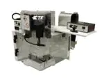
AMP 3K* Terminating Machine 1725950-[ ] and
AMP 5K* Terminating Machine 1725900-[ ]
409-10047
30 JAN 12 Rev J
............................ 2
ORIGINAL INSTRUCTIONS
customer manual
SAFETY PRECAUTIONS READ THIS FIRST !
Customer Manual
1. INTRODUCTION . . . . . . . . . . . . . . . . . . . . . . . . . . . . . . . . . . . . . . . . . . . . . . . . . . . . . . . . 3
2. DESCRIPTION. . . . . . . . . . . . . . . . . . . . . . . . . . . . . . . . . . . . . . . . . . . . . . . . . . . . . . . . . . 4
2.1. Functional Description . . . . . . . . . . . . . . . . . . . . . . . . . . . . . . . . . . . . . . . . . . . . . . . . 4
2.2. Electrical Description . . . . . . . . . . . . . . . . . . . . . . . . . . . . . . . . . . . . . . . . . . . . . . . . . 6
2.3. Machine Guard . . . . . . . . . . . . . . . . . . . . . . . . . . . . . . . . . . . . . . . . . . . . . . . . . . . . . . 7
3. RECEIVING INSPECTION AND INSTALLATION . . . . . . . . . . . . . . . . . . . . . . . . . . . . . . . 8
3.1. Receiving Inspection . . . . . . . . . . . . . . . . . . . . . . . . . . . . . . . . . . . . . . . . . . . . . . . . . 8
3.2. Installation . . . . . . . . . . . . . . . . . . . . . . . . . . . . . . . . . . . . . . . . . . . . . . . . . . . . . . . . . 8
3.3. Considerations Affecting the Placement of Bench Machines . . . . . . . . . . . . . . . . . . . 9
4. OPERATION . . . . . . . . . . . . . . . . . . . . . . . . . . . . . . . . . . . . . . . . . . . . . . . . . . . . . . . . . . . 10
4.1. Control Panel Operation . . . . . . . . . . . . . . . . . . . . . . . . . . . . . . . . . . . . . . . . . . . . . . . 10
4.2. Applicator Installation . . . . . . . . . . . . . . . . . . . . . . . . . . . . . . . . . . . . . . . . . . . . . . . . . 10
4.3. Setup . . . . . . . . . . . . . . . . . . . . . . . . . . . . . . . . . . . . . . . . . . . . . . . . . . . . . . . . . . . . . 13
4.4. Mode Selection and Operation . . . . . . . . . . . . . . . . . . . . . . . . . . . . . . . . . . . . . . . . . . 13
4.5. Crimp Height Adjustment . . . . . . . . . . . . . . . . . . . . . . . . . . . . . . . . . . . . . . . . . . . . . . 15
4.6. End-Feed/Side-Feed Applicator Conversion . . . . . . . . . . . . . . . . . . . . . . . . . . . . . . . 15
5. PREVENTIVE MAINTENANCE . . . . . . . . . . . . . . . . . . . . . . . . . . . . . . . . . . . . . . . . . . . . . 16
5.1. Cleaning . . . . . . . . . . . . . . . . . . . . . . . . . . . . . . . . . . . . . . . . . . . . . . . . . . . . . . . . . . . 16
5.2. Lubrication . . . . . . . . . . . . . . . . . . . . . . . . . . . . . . . . . . . . . . . . . . . . . . . . . . . . . . . . . 16
6. ADJUSTMENTS . . . . . . . . . . . . . . . . . . . . . . . . . . . . . . . . . . . . . . . . . . . . . . . . . . . . . . . . 17
6.1. Measuring the Shut Height . . . . . . . . . . . . . . . . . . . . . . . . . . . . . . . . . . . . . . . . . . . . . 17
6.2. Shut-Height Adjustment . . . . . . . . . . . . . . . . . . . . . . . . . . . . . . . . . . . . . . . . . . . . . . . 18
6.3. Crimp Height Adjustment Using Precision Adjustment Mechanism (If Equipped) . . . 19
6.4. Guard Insert Adjustment. . . . . . . . . . . . . . . . . . . . . . . . . . . . . . . . . . . . . . . . . . . . . . . 20
7. MACHINE OPTIONS AND INSTALLATION . . . . . . . . . . . . . . . . . . . . . . . . . . . . . . . . . . . 22
7.1. Installation of Work Light Assembly Kit 1424264-1 . . . . . . . . . . . . . . . . . . . . . . . . . . 22
7.2. Installation of Work Light Assembly Kit 1424264-1 (Inside the Guard) . . . . . . . . . . . 24
7.3. Installation of Batch Counter Kit 1424267-1 . . . . . . . . . . . . . . . . . . . . . . . . . . . . . . . . 29
7.4. Installation of Air Feed Kit 1424266-1 . . . . . . . . . . . . . . . . . . . . . . . . . . . . . . . . . . . . 31
7.5. Installation of Precision Adjustment Kit 1424208-1 . . . . . . . . . . . . . . . . . . . . . . . . . . 33
8. TROUBLESHOOTING. . . . . . . . . . . . . . . . . . . . . . . . . . . . . . . . . . . . . . . . . . . . . . . . . . . . 33
9. ROHS INFORMATION. . . . . . . . . . . . . . . . . . . . . . . . . . . . . . . . . . . . . . . . . . . . . . . . . . . . 33
10. REVISION SUMMARY. . . . . . . . . . . . . . . . . . . . . . . . . . . . . . . . . . . . . . . . . . . . . . . . . . . 33
© 2012 Tyco Electronics Corporation, a TE Connectivity Ltd. Company
All Rights Reserved
*Trademark
TOOLING ASSISTANCE CENTER
1-800-722-1111
This controlled document is subject to change.
For latest revision and Regional Customer Service,
visit our website at www.te.com
TE Connectivity, TE connectivity (logo), and TE (logo) are trademarks. Other logos, product and/or Company names may be trademarks of their respective owners.
1 of 33
LOC B
�409-10047
DANGER
STOP
SAFETY PRECAUTIONS AVOID INJURY
Safeguards are designed into this application equipment to protect operators and maintenance personnel from
most hazards during equipment operation. However, certain safety precautions must be taken by the operator
and repair personnel to avoid personal injury, as well as damage to the equipment. For best results, application
equipment must be operated in a dry, dust-free environment. Do not operate equipment in a gaseous or
hazardous environment.
•
•
•
•
•
•
Carefully observe the following safety precautions before and during operation of the equipment:
•
•
•
NEVER wear loose clothing or jewelry that may catch in moving parts of the application equipment.
ALWAYS wear appropriate ear protection.
ALWAYS wear approved eye protection when operating powered equipment.
ALWAYS keep guard(s) in place during normal operation.
ALWAYS insert power plug into a properly grounded receptacle to avoid electrical shock.
ALWAYS turn off the main power switch and disconnect electrical cord from the power source when
performing maintenance on the equipment.
NEVER insert hands into installed application equipment.
NEVER alter, modify, or misuse the application equipment.
TOOLING ASSISTANCE CENTER
CALL TOLL FREE 1-800-722-1111 (CONTINENTAL UNITED STATES AND PUERTO RICO ONLY)
The Tooling Assistance Center offers a means of providing technical assistance when required.
In addition, Field Service Specialists are available to provide assistance in the adjustment or repair of the
application equipment when problems arise which your maintenance personnel are unable to correct.
INFORMATION REQUIRED WHEN CONTACTING THE TOOLING ASSISTANCE CENTER
When calling the Tooling Assistance Center regarding service to equipment, it is suggested that a person familiar
with the device be present with a copy of the manual (and drawings) to receive instructions. Many difficulties can
be avoided in this manner.
When calling the Tooling Assistance Center, be ready with the following information:
1.
2.
3.
4.
5.
6.
7.
8.
9.
10.
Rev J
Customer name
Customer address
Person to contact (name, title, telephone number, and extension)
Person calling
Equipment number (and serial number if applicable)
Product part number (and serial number if applicable)
Urgency of request
Nature of problem
Description of inoperative component(s)
Additional information/comments that may be helpful
2 of 33
�409-10047
AMP 5K 1725900-[ ]
AMP 3K 1725950-[ ]
Fan
Figure 1
1. INTRODUCTION
This manual contains information on operation, preventive maintenance, and adjustments of the AMP 3K and
AMP 5K Terminating Machines 1725950-[ ] and 1725900-[ ] respectively. See Figure 1.
Both series machines (AMP 3K and AMP 5K) contain separate machines to produce a 30 mm stroke or a 41.28
mm stroke.
Descriptions in this manual pertain to the controls and adjustments on the AMP 3K and AMP 5K machines only.
The specifications and requirements for the AMP 3K and AMP 5K Terminating Machines are as listed below:
Deflection:
0.13 mm [.0046 in.] Maximum per 4,448 Newtons [1,000 lb] Crimp Force
Noise (Model 3K Series):
Less than 76 dBa Typical at operator position with standard mechanical
feed applicator
Noise (Model 5K Series):
Less than 80 dBa Typical at operator position with standard mechanical
feed applicator
Weight:
68.86 Kilograms [143 lb]
Height:
510 mm [20 in.] without reel supports
Electrical:
100-240 Vac, 50/60 Hz, Single-Phase Current
Air:
620-760 kPa [90-100 psi], 2.83 liters/sec (6 scfm) When required for use
with air-feed applicators
Physical Environment:
Rev J
Temperature: 4.4°-40° C [40°-104° F]
Relative Humidity: Less than 95% (non-condensing)
Transportation and Storage: Store in a clean, dry environment after coating
all surfaces lightlywith a rust preventing oil.
3 of 33
�409-10047
The various applicators that can be used in the machines are covered in applicator instruction sheets packaged
with each applicator. Applicator instruction sheets provide information on applicator installation, care, and
adjustment.
When reading this manual, pay particular attention to DANGER, CAUTION, and NOTE statements.
DANGER
Denotes an imminent hazard which may result in moderate or severe injury.
STOP
CAUTION
!
NOTE
i
NOTE
i
Denotes a condition which may result in product or equipment damage.
Highlights special or important information.
Dimensions in this manual are in metric units [with U.S. customary units in brackets].
2. DESCRIPTION
The AMP 3K/40 and AMP 5K/40 Terminating Machines were designed to be used as stand-alone semiautomatic bench units. They are assembled with metric hardware.
These machines accepts a wide variety of miniature (mini) quick-change applicators, with minor adjustments,
thus providing a great selection of terminals for many applications. Figure 2 lists changeover cams required to
run 1 1/8-in. stroke cams (for AMP-O-LECTRIC* Model "K" terminating machines) and 1 5/8-in. stroke cams (for
Model "T" and Model "G" Terminating machines) in the machines.
ORIGINAL APPLICATOR
1 1/8-in. Stroke Applicator for
Model “K" Terminating Machine
CHANGEOVER CAMS FOR
THE MACHINES
FEED TYPE
1 5/8-in. [41.25mm]
Stroke Machines
1 1/8 -in [30mm]
Stroke Machines
Pre-Feed
690602-6
---
Post-Feed
690501-4
---
1 5/8-in. Stroke Applicator for
Model “T" and Model “G" Terminating
Machines
Pre-Feed
---
690602-5
Post-Feed
---
690501-3
Heavy-Duty Industrial (HD-I)
Applicator
Pre-Feed/
Post-Feed
Refer to the HD-I Applicator customer drawing for part numbers.
Figure 2
2.1. Functional Description
These machines provide the force required to crimp terminals in the applicator. A terminal is attached to the wire
by placing the wire in the crimp area and pressing the foot switch. The machine consists of four functional areas:
1. The motor group includes a dc motor which drives a crankshaft. The motor is activated each cycle and
rotates the crankshaft one full revolution. A motor access cover, located on the end of the motor, covers a hex
key which allows the motor to be cycled manually. See Figure 3.
2. The crankshaft-ram group covers the motor rotational force to the up-and-down action of the ram for
driving the applicator during the crimping cycle.
Rev J
4 of 33
�409-10047
DC Motor
Crankshaft
Motor Access Cover
Figure 3
Shown with Optional
Precision Crimp Height
Adjustment Mechanism
Quick-Release
T-Handle
Base Plate for Machines -1,
-2, -5, -6, -7, -8, -9,-12, -13,
and -14
Base Plate for Machines
-3 and -4
Alternate Rear Stop
Mounting Position
Figure 4
Rev J
5 of 33
�409-10047
3. The base plate provides the mounting surface on which the applicator is installed. The quick-release
latching feature on Machines -1, -2, and -5, through -13 permit fast, easy installation and removal of the
applicator. Note that Machines -3 and -4, restricted to Asia/Pacific market, do not include the quick-release
latching feature. See Figure 4.
2.2. Electrical Description
The 1725950-[ ] and 1725900-[ ] machine electrical components consist of the operator control panel, the motor,
and the CPU/motor controller package. The machine operates on 100/240 Vac, 50/60 Hz, single-phase current
with ground. The machine will automatically detect the supply voltage and adjust the controller accordingly.
The AMP 5K Terminating Machine CPU/motor controller packages contain a fan to cool the motor assembly.
(See Figure 1.) This fan runs whenever the main power switch is on.
The operator control panel (Figure 5) is mounted on the left side of the machine frame. The control panel
consists of two indicator lights, one jog button, and one speed control knob, with icons depicting each function.
See Paragraph 4.1 for control panel operation.
Yellow
Indicator
Guard Open Icon
Speed Control Knob
Jog Button
Speed Control
Icon
Green
Indicator
Machine
Ready
Icon
Fault
Icon
Batch Counter Kit
Guard Disabled
Icon
Jog Button Icon
Figure 5
Rev J
6 of 33
�409-10047
A main power switch/circuit breaker (Figure 6) is located on the back of the machine. This switch connects ac
power to the control system. The CPU/motor controller is located behind the back cover of the machine. It is a
modular unit that contains all of the electronics necessary to operate the machine. See Figure 6.
Reel Support Hole
DC Motor
Motor
Access
Cover
Terminal
Strip Guide
Back Cover
CPU/Motor Controller
(Behind Back Cover)
Power Switch/
Circuit Breaker
Figure 6
2.3. Machine Guard (Figure 7)
A guard is installed to provide protection for the operator while maintaining proper visibility of the work area. The
guard swings open to allow easy access for applicator installation and setup. A safety interlock on the guard
prevents the machine from cycling if the guard door is open during production operation.
NOTE
Machines -4, -8, -11, and -13 do not include the safety interlock feature. To avoid personal injury, remember that the power
is not automatically shut off when the guard doors are opened.
i
Rev J
7 of 33
�409-10047
Hole for Customer
Supplied Lift Ring
Machine
Guard
Shown with Optional
Precision Crimp Height
Adjustment Mechanism
Shown with Safety
Interlock (Not on Machines
-4, -8, -11, and -13)
Quick-Release T-Handle
for Machines -1, -2, -5, -6, 7, -8, -9, -12, and -13
Figure 7
3. RECEIVING INSPECTION AND INSTALLATION
3.1. Receiving Inspection
These machines are thoroughly inspected during and after assembly. A final series of inspections is made to
insure the proper machine functioning before packaging and shipping.
To protect against damage that may have occurred during shipment, remove the machine from the crate
(Paragraph 3.2) and carefully inspect the machine for damage. If damage is evident, file a claim against the
carrier and notify TE immediately.
3.2. Installation
Remove all mounting bolts securing the machine to the shipping pallet. Install lift ring (see Figure 7) on top of the
machine.
NOTE
Lift ring (M1220 eye bolt) is customer supplied.
i
NOTE
Install the lift ring carefully. A 19.05-mm [.75-in.] thread length engagement is required for the lift ring to support the
machine.
i
Attach a suitable hoist to the lift ring, lift the machine, and place it in the selected operating location.
Insert the reel support post into the appropriate hole on top of the machine (Figure 6) until the roll pin engages a
groove in the machine frame.
Rev J
8 of 33
�409-10047
Attach the terminal strip guide included with the machine with the two thumbscrews supplied. Mount the guide
on the left guard for side-feed applicators. Mount the guide on the right guard for end-feed applicators.
Connect the power cord to a suitable electrical supply.
NOTE
The machine will automatically detect the supply voltage and adjust the controller accordingly.
i
NOTE
i
Machines exported to Europe will be installed by TE service engineers. These engineers will verify that the electrical and
pneumatic connections are correct. Both pneumatic and electrical connections must be installed in a way that provides a
lockable isolation switch for hard-wired or direct piped machines. This is necessary to interrupt power to the machine for
setup or maintenance.
3.3. Considerations Affecting Placement of Bench Machines
The location of the machine in relation to the operator's position is extremely important in terms of both safety
and maximum efficiency. Studies have repeatedly shown that operator fatigue will be reduced, and greater
efficiency achieved, if:
1. The bench is of appropriate height, preferably with sound-deadening rubber mounts;
2. The machine is properly located on the bench with ample work areas on both sides to facilitate work flow;
3. the operator uses a swivel chair with padded seat and back rest which are independently adjustable; and
4. the foot switch, on machines so equipped, is placed on a rubber mat to maintain its movability, while
preventing it from sliding unintentionally.
Figure 8 illustrates proper machine location and operator position and the following:
A. Bench
The bench to be used should be of sturdy construction, preferably with rubber mounts to minimize noise. A
height of 762 to 812.8 mm [30 to 32 in.] is the most suitable for operator comfort and convenience. This height
allows the operator to rest both feet on the floor, thereby providing for the shifting of weight and leg position.
B. Machine Location on Bench
The machine should be located near the front of the bench with the "target area" (tooling area where the
product is applied) not more than 152.4 to 203.2 mm [6 to 8 in.] from the front edge. This location will eliminate
unnecessary operator motion and help to avoid back strain and fatigue.
Orientation of the machine should be such that the "target area" is facing the front of the bench and is parallel
to the front edge (access to the back of the machine MUST also be provided).
NOTE
Machines have provisions for being bolted to the bench.
i
C. Operator's Chair
The operator's chair should swivel, and should have independent seat height and back rest adjustments. The
seat and back rest should be padded, and the back rest should be large enough to provide support both
above and below the waist line.
In use, the chair should be far enough under the bench so that the operator's back is straight and is supported
by the back rest.
D. Foot Switch
When the operator is correctly positioned in front of a machine equipped with a foot switch, the foot should
rest on the switch comfortably. The foot switch should be movable, so that its location can be readily changed
when the operator shifts position to minimize fatigue. Placing the switch on a rubber mat keeps it movable
while preventing unintentional sliding.
Rev J
9 of 33
�409-10047
The preferred foot switch location varies to some extent among operators. Some operators prefer the switch
located so that their foot rests on the switch when their feet are in the natural sitting position (calf of leg
perpendicular to the foot). Others prefer the leg to be slightly in front of the natural position. The important
thing to remember is that the foot should be at approximately 90_ (right angle) to the calf when resting on the
switch. Those operators who prefer the foot switch slightly in front of the natural position may require a
wedge-shaped block placed under it.
Figure 8
E. Scrap Removal
A suggested method of scrap removal: place a tray on the right side of the machine, under the cast slot in the
frame, to capture the scrap chips.
4. OPERATION
4.1. Control Panel Operation
The basic control panel operation is as described in Figure 9. The control panel will be used to set up and
operate the machine (see Paragraphs 4.3 and 4.4).
4.2. Applicator Installation
NOTE
i
These instructions apply to Machines -1, -2, -5, -6, -7, -8, -9, -12, and -13.. Since Machines -3 and -4 do not contain a
quick-release feature, they do not contain a quick-change mounting base plate. The appropriate additional baseplate
tooling will be required on Machines -3 and -4. The -10 and -11 machines use a swing handle to release applicators.
Installation is in the reverse order of removal.
Install the proper applicator in the quick-change mounting base as follows:
CAUTION If the machine is equipped with a precision adjustment feature, make sure that the precision adjustment lever has been
returned to the "0" position before installing the applicator. Be sure that the applicator has the proper feed cam prior to
installation.
!
NOTE
Applicators from AMP-O-LECTRIC Model "K" terminating machine and Model "T" terminating machine can be used in
these machines by using a special replacement cam. Refer to Figure 2.
i
1. Loosen the quick-release T-handle (see Figure 5) and slide the applicator base clamp down.
2. Place the applicator on the quick-change base plate, then slide it back until the two notches in the
applicator base engage the stops at the back of the quick-change base plate. At the same time, guide the ram
post into the ram post adapter.
Rev J
10 of 33
�409-10047
3. Slide the applicator base clamp UP and re-tighten the quick-release T-handle to secure the applicator in
place.
NOTE
i
When using Applicator 567200-2 (originally intended for use with AMP-O-LECTRIC Model "K" terminating machine),
loosen the quick-release T-handle, slide down the applicator base clamp, and remove the rear stop located on the left side
of the base plate. Install the rear stop (PN 354561-1), supplied with the air feed kit, at the alternate mounting position on
the base plate. See Figure 4.
4. Set the crimp height and insulation crimp discs so that the letters and numbers on the applicator pad align
with the front pad on the ram post adapter.
5. If the applicator is an air-feed type, connect the airlines to the valves located on the back of the machine.
NOTE
Quick Disconnect Coupling 23238-1 is required to run air-feed applicators.
i
6. Adjust the reel support for side-feed or end-feed product, depending on the applicator being used.
7. Mount the terminal strip guide on the left sheet metal guard for side-feed product, or on the right sheet
metal guard for end-feed product, depending on the applicator being used.
8. Mount the terminal reel on the reel support. Thread the terminal strip through the guard and into the
applicator according to the instruction sheet included with the applicator. If necessary, adjust the lubricator
bowl.
9. Align the product reel to the applicator by adjusting the reel flanges.
10. Close the guard.
NOTE
The guard door must be closed in order to operate the machine, unless you are in the Jog (With Guards Disabled) Mode.
See Paragraph 4.4,C.
i
DANGER Opening the guard door will not disable Machine-4, -8, -11, and -13.
STOP
Rev J
11 of 33
�409-10047
Jog Button
Yellow Indicator
Speed Control
Knob
Green Indicator
Machine Ready Icon
Speed Control Icon
Fault Icon
Jog Button Icon
Optional Batch Counter
Guard Open Icon
Guard Disabled Icon
Figure 9
Rev J
12 of 33
�409-10047
4.3. Setup
Install a miniature applicator and terminals according to Paragraph 4.1.
1. Turn on the main power using the switch located on the back of the machine.
2. Jog the machine (as described in Paragraph 4.3, B) through a complete crimp cycle.
NOTE
Machine should be able to jog through the terminal and wire at maximum jog speed to determine crimp capacity.
i
3. Inspect the crimped terminal to verify that the terminal is being positioned properly within the applicator.
4. Correct for any positioning errors according to the applicator instruction sheet, and repeat Steps 2 and 3
until a terminal is properly positioned.
5. Place a prepared wire in the crimp area and press the foot switch.
6. Inspect the completed crimp and make adjustments as necessary.
4.4. Mode Selection and Operation
The three basic modes of operation for these machines include: Full-Cycle, Jog, and Jog (With Guards
Disabled).
A. Full-Cycle Mode
Depressing the footswitch (with the guard closed) causes the crankshaft to be rotated (at a speed defined by
the speed control knob), through a complete revolution. This completes one full machine cycle.
B. Jog Mode (Figure 9)
Pressing the Jog button causes the crankshaft to be rotated at a default-reduced speed in the forward
direction until the Jog button is released or the crankshaft completes the cycle. If the Jog button is released in
mid-cycle and pressed again, the crankshaft will continue to rotate in the forward direction at the default
reduced speed. If the machine does not complete the cycle, either adjust the speed control knob (as
described below), or complete the cycle using the footswitch (at a speed determined by the speed control
knob) after the Jog button has been pressed and released.
Holding the Jog button down for more than five seconds will cause the machine to "err." To clear the error,
"power down" the machine, clear the problem area, and then "power up" the machine again. An alternate
method of clearing the error is to hold down the foot pedal until the green status indicator stops flashing. If the
motor is stalled, it may be necessary to manually cycle the machine to the home position. Refer to the
CAUTION and DANGER statements below for the proper manual cycling procedure.
CAUTION While in the Jog mode, attempting to complete a crimp cycle with terminals and wire in the applicator may cause the motor
to stall. Although the machine can terminate some smaller terminals and wire, it may be necessary to turn "off" the
machine
and manually cycle the machine to the home position. Manually cycle the machine by removing the access cover
!
on the end of the motor (Figure 6), engaging the hex key with a 6-mm hex wrench, and rotating the key to manually rotate
the motor.
DANGER To avoid personal injury, be sure to remove the hex wrench before operating the machine under power. Be sure to replace
the access cover.
STOP
DANGER To avoid personal injury, exercise caution when jogging or operating the -4, -8, -11, and -13 machines. These machines
will jog/cycle with the guards in the open or closed position.
STOP
Rev J
13 of 33
�409-10047
Adjusting the Speed Control Knob
The default speed of the crankshaft in the Jog Mode is set to a minimum initial value which is not defined by
the initial position of the speed control knob. Adjusting the speed upwards enables jogging at speeds greater
than the default in case greater speeds are required to complete a cycle. To cause the crankshaft to rotate at
other than the initial default speed, the speed control knob must be rotated completely counterclockwise, then
rotated back clockwise to the desired speed setting. If the Jog button is depressed within three seconds of
setting the speed control knob, the crankshaft will rotate at the speed defined by the position of the speed
control knob. The new speed setting will remain active for a maximum of three seconds after the Jog button is
released, or until the crankshaft completes the cycle. If the cycle is not complete and the Jog button is again
pressed within three seconds from its release, the crankshaft will rotate at the speed defined by the position of
the speed control knob. Failure to push the Jog button within the three seconds of its release will cause the
crankshaft jog speed to revert back to the initial minimum default value. After the Jog button is released, the
speed control knob can be rotated in either direction to increase or reduce the crankshaft jog speed, but Jog
button must be activated again within three seconds of the release or the speed will revert back to minimum
default speed. The speed control knob can be reset as many times as desired.
NOTE
The ram may drift downward if the Jog button is released in mid-stroke.
i
C. Jog (With Guards Disabled) Mode (Figure 9)
NOTE
Since the -4, -8, -11, and -13 machines do not employ safety interlock switches in the guard doors, this section does not
apply to them.
i
NOTE
The foot pedal will NOT initiate cycling in this mode.
i
DANGER To avoid personal injury, be very careful of moving mechanisms when jogging the machine with the guards open.
STOP
This mode allows maintenance and setup personnel to slowly rotate the crankshaft with the guard door open.
To activate this mode, turn "off" power, and open the guard door. Turn the power back "on" and, immediately
after the machine ready and guard disable indicators flash "on", press and hold the Jog button. The guard
disable indicator will flash at a rate of two flashes per second, indicating that the guard has been disabled.
Pressing the Jog button will rotate the crankshaft at a reduced rate until the Jog button is released or the
crankshaft completes one cycle.
Pressing the Jog button causes the crankshaft to be rotated at a default-reduced speed in the forward
direction until the Jog button is released or the crankshaft completes the cycle. If the Jog button is released in
mid-cycle and then pressed again, the crankshaft will continue to rotate in the forward direction at the default
reduced speed. If the machine does not complete the cycle, see "Adjusting the Speed Control Knob," below.
Holding the Jog button for more than five seconds and not completing the cycle may cause the machine to
"err." To clear the error, "power down" the machine, clear the problem area, and then "power up" the machine.
Another method of clearing an error is to hold down the foot pedal until the green status indicator stops
flashing. If the motor is stalled, it may be necessary to manually cycle the machine to the home position. See
the CAUTION and DANGER statements above for manual cycling.
Adjusting the Speed Control Knob
The default speed of the crankshaft in the Jog Mode is set to a minimum initial value which is not defined by
the initial position of the speed control knob. Adjusting the speed upwards enables jogging at speeds greater
than the default in case greater speeds are required to complete a cycle. To cause the crankshaft to rotate at
other than the initial default speed, the speed control knob must be rotated completely counterclockwise, then
Rev J
14 of 33
�409-10047
rotated back clockwise to the desired speed setting. If the Jog button is depressed within three seconds of
setting the speed control knob, the crankshaft will rotate at the speed defined by the position of the speed
control knob. The new speed setting will remain active for a maximum of three seconds after the Jog button is
released, or until the crankshaft completes the cycle. If the cycle is not complete and the Jog button is again
pressed within three seconds from its release, the crankshaft will rotate at the speed defined by the position of
the speed control knob. Failure to push the Jog button within the three seconds of its release will cause the
crankshaft jog speed to revert back to the initial minimum default value. After the Jog button is released, the
speed control knob can be rotated in either direction to increase or reduce the crankshaft jog speed, but Jog
button must be activated again within three seconds of the release or the speed will revert back to minimum
default speed. The speed control knob can be reset as many times as desired.
The machine will exit the Jog (With Guards Disabled) Mode whenever the guards are closed or the power is
turned "off."
NOTE
i
The speed control knob in Figure 9 also adjusts the air feed timing. Normally the air feed timing is set at 280 ms. When the
speed control is set at less than 50% of its maximum setting (pointing straight down or counterclockwise from pointing
straight down), the air feed timing changes to 440 ms. This is done to accommodate applicators that have longer than
normal air cylinders.
The green flashing status indicator flashes a specific number of times to represent a corresponding fault. For
example, the green status indicator will flash two times (each followed by a one second pause) to indicate that
the machine guard opened while the machine was running. Refer to Figure 10.
FAULT INDICATOR CODE
(Number of Consecutive Flashes)
MACHINE FAULT
2
The guard opened while the motor was running.
3
The guard must be closed before proceeding.
4
Motion from top dead center (TDC) was not detected.
5
The TDC switch was not sensed.
6
A bad PWM IGBT was detected.
7
A bad Jog push button input was detected.
8
A bad footswitch input was detected.
9
A bad DC bus relay was detected.
10
A bad jog enable input was detected.
11
The line voltage is not within specifications.
12
A bad spare input was detected.
Figure 10
4.5. Crimp Height Adjustment
On machines that do not include the precision adjustment feature, the crimp height must be adjusted at the
applicator. Refer to the instructions provided with the applicator to perform this adjustment. Refer to Paragraph
6.3 for procedures to adjust the crimp height using the machine precision adjustment feature.
4.6. End-Feed/Side-Feed Applicator Conversion
When changing from an end-feed applicator to a side-feed applicator (or from a side-feed applicator to an endfeed applicator), the reel support assembly must be moved to the opposite side of the machine. With the
terminal reel removed, lift and rotate the reel support bar to the opposite side of the machine. Mount the terminal
reel on the reel support and load the terminal strip into the applicator. Remove the metal terminal lead-in and
thumbscrews and move to the opposite side of the machine. Move the machine lubricator bowl to the opposite
side of the machine as required.
NOTE
Lubricator Bowl Assembly 354550-1 is an optional accessory.
i
Rev J
15 of 33
�409-10047
5. PREVENTIVE MAINTENANCE
Preventive maintenance will keep the machine in good working order and ensure maximum reliability and
service from all of its components.
DANGER To avoid personal injury, electrical and pneumatic power must be DISCONNECTED at the source prior to maintenance.
STOP
5.1. Cleaning
Clean any debris from the applicator area daily.
DANGER Compressed air used for cleaning must be reduced to less than 207 kPa [30 psi] and effective chip guarding and personal
protective equipment (including eye protection) must be used.
STOP
If an air-feed assembly is installed, check and replace the air filter element if necessary.
Wipe off the guards with a clean soft cloth.
CAUTION DO NOT USE ANY SOLVENT TO CLEAN THE GUARDS. Solvent could damage the guards.
!
5.2. Lubrication
The moving parts of the machine require regular lubrication to ensure reliable service and long life. Use only a
good grade NLGI No. 2 grease.
NOTE
Contact TE engineering for preferred lubricants.
i
NOTE
For operation in temperatures below 10°C [50°F], it will be necessary to use a No. 1 grease.
i
Using a grease gun, apply grease every 250,000 cycles to the fittings at the following locations and as shown in
Figure 11:
•
•
•
the left side of the ram assembly;
the right side of the ram assembly;
the left side of the frame just behind the ram assembly at two places; and
NOTE
Give one pump of grease while the ram is near the top of its stroke and one pump of grease while the ram is near the
bottom of its stroke for best distribution of grease around the bearing.
i
•
Rev J
the crimp height adjuster pivot pin.
16 of 33
�409-10047
Shown with Optional Precision Crimp
Height Adjustment Mechanism
Lubrication
Points
Lubrication
Points
Figure 11
6. ADJUSTMENTS
The following adjustments are necessary to maintain the machine in operating condition, and to set up the
machine after replacing parts.
DANGER To avoid personal injury, ALWAYS disconnect electrical and air supplies before performing adjustments.
STOP
6.1. Measuring the Shut Height
The shut height is the distance between the bottom surface of the ram post adaptor and the top surface of the
machine base plate as shown in Figure 12.
NOTE
Shut Height Gage 679655-[ ] (see the table in Figure 12) is recommended for measuring shut height (refer to 408-8535 for
instructions on use of the gage).
i
1. .If installed, adjust the manual precision adjustment lever to the "0" setting.
2. Remove the access cover (Figure 6) on the end of the motor.
3. Insert a 6-mm hex wrench into the end of the motor until it completely engages the hex key in the end of the
motor. Use the hex wrench to manually rotate the motor.
DANGER Be sure to remove the hex wrench before operating the machine.
STOP
Rev J
17 of 33
�409-10047
Shown with Optional Precision
Crimp Height Adjustment Mechanism
SHUT HEIGHT GAGE
PART NUMBER
MACHINE PART NUMBERS
(91725950-[ ] and 1725900-[ ])
SHUT HEIGHT DIMENSIONS
APPLICATOR TYPE
679655-2
-1 Through -9, -12, and -13
135.79 mm +/- 0.025 mm
[5.346 +/- .0010 In.]
AMP
679655-3
-10, -11, and -14
119.50 +/- 0.025 mm
[4.7047 +/-. .0010 In.]
JAM
Figure 12
4. Follow the procedure for measuring the shut height as described in 408-8535.
5. Install the access cover onto the end of the motor.
6.2. Shut-Height Adjustment
The shut height is pre-set at the factory and should not require further adjustment unless it is necessary to
replace parts. Before you make any changes to the machine, contact your local field service representative, or
call the Tooling Assistance Center at 1-800-722-1111.
CAUTION NEVER attempt to adjust the shut height without FIRST trying an applicator that is known to produce terminations of the
correct crimp height. If this applicator produces correct terminations, the trouble is in the original applicator and the shut
height MUST NOT BE CHANGED.
!
If it is determined that the shut height must be adjusted, use the following procedure:
DANGER To avoid personal injury, ALWAYS turn "off" the machine and disconnect the power supply to the machine before making
any adjustments. If applicator is an air-feed type, DISCONNECT air lines to valve located on the right side of the machine.
STOP
1. Check shut height as described in Paragraph 6.1.
2. If the shut height is incorrect, refer to Figure 13, and proceed as follows:
a. Remove the two socket head cap screws which secure the ram post adaptor. Remove the ram post
adaptor and shims. Change the shim thickness as required to adjust the shut height. Shims contain .051mm [.002-in.] peel-type laminations.
Rev J
18 of 33
�409-10047
NOTE
If additional shims are required, they can be ordered using the numbers 1338618-1 (for 41.25 mm stroke machines) or
1424680-1 (for 30 mm stroke machines).
i
b. Re-install the ram post adaptor. Insert both screws in the ram post adaptor and place the shims over
the screws and onto the adaptor post.
c. Re-install the socket head cap screws into the ram assembly to secure the ram post adaptor. Retighten the screws.
3. Repeat Steps 1 and 2 as necessary until the proper shut height is attained.
NOTE
i
The miniature applicator is an integrated assembly consisting of upper tooling, lower tooling, and adjustment capability.
The applicator requires a fixed shut height; that is, the distance between the bottom of the ram and the base mount when
the ram is FULLY bottomed. The required adjustments for crimp height are made by using the wire and insulation discs
within the applicator. Refer to the instruction sheet supplied with the applicator for adjustment procedures.
6.3. Crimp Height Adjustment Using Precision Adjustment Mechanism (If Equipped)
NOTE
The precision adjustment mechanism is available on most machines, with the exception of -1 and -5 machines; as well as
Field Retrofit Kit 1424208-1 for Machines -1 and -5.
i
DANGER To avoid damaging the applicator, ALWAYS return the precision adjustment lever to the "0" position when finished using
the applicator.
STOP
1. Adjust the manual precision adjustment lever to "0" by pulling the lever away from the pivot pin. Lock the
lever in place by releasing it.
2. Install the applicator into the machine as described in Paragraph 4.1.
3. Cycle the machine to crimp three sample terminations. Check the crimp height of the samples. If the crimp
heights are not correct, adjust the crimp height according to Step 4.
4. Adjust the crimp height by moving the precision adjustment lever:
a. to the right to increase the crimp height; or
b. to the left to decrease the crimp height.
NOTE
Moving the precision adjustment lever in either direction will change the crimp height by approximately 0.013 mm [.0005
in.] per step.
i
5. Repeat Steps 3 and 4 until the appropriate crimp height is obtained.
DANGER To avoid damaging the applicator, ALWAYS return the manual precision adjustment lever to the "0" position when finished
using the applicator.
STOP
Rev J
19 of 33
�409-10047
Manual Precision
Adjustment Lever
Figure 13
6.4. Guard Insert Adjustment
A guard insert is supplied with the machine. Some applications may require a special insert. See Figure 14 for
available guard inserts.
The guard contains two slots into which the inserts can be placed: the rear slot places the insert close to the
applicator; the front slot places the insert farther away from the applicator. The type of insert used determines
which slot is to be used. An insert placed into the wrong slot cannot be secured in place.
NOTE
Some special inserts are designed to mount in the standard insert slot. These inserts have the threaded holes at the top
corners and should be installed according to the instructions for the standard insert.
i
Rev J
20 of 33
�409-10047
GUARD INSERT
DIMENSION
PART NUMBER
DESCRIPTION
A
B
354529-2
Standard (Away from the Applicator)
7.80 [.307]
6.35 [.250]
1-679532-0
Standard (Close to the Applicator) - Shipped with the Machine
6.22 [.245]
5.08 [.200]
679994-2
Near Tape
6.35 [.250]
6.35 [.250]
679995-2
Away from Tape
8.74 [.344]
6.35 [.250]
Figure 14
A. Standard Guard Insert 1-679532-0 and Guard Insert 679994-2
1. Slide the insert into the rear slot of the guard door. Secure the insert to the door with two screws placed
through the large square holes in the left guard door and into the threaded holes in the top of the insert. Do not
tighten the screws.
2. Move the insert horizontally and vertically as needed to align the slot with the crimp area of applicator.
3. Tighten the screws.
B. Guard Insert 354529-2 and Guard Insert 679995-2
1. Slide the insert into the front slot of the guard door. Secure the insert to the door with two screws placed
through the large square holes of the insert and into the threaded holes in the bottom of the left guard door.
Do not tighten the screws.
2. Move the insert horizontally and vertically as needed to align slot with crimp area of the applicator.
3. Tighten the screws.
Rev J
21 of 33
�409-10047
7. MACHINE OPTIONS AND INSTALLATION
The following machine options are available for the AMP 3K and AMP 5K machines:
PART NUMBER
DESCRIPTION
PURPOSE
1424264-1
Work Light Kit (64111 Osram/Sylvania)
Provides lighting to the work area
1424266-1
Air Feed Valve Kit with 40-mm [15/8-in.] Stroke
Required to run 40-mm [15/8-in.] stroke applicators
1424266-2
Air Feed Valve Kit with 30-mm [11/8-in.] Stroke
Required to run 30-mm [11/8-in.] stroke applicators
1424267-1
Batch Counter Kit
Counts terminations
1424208-1
Precision Adjust Field Retrofit Kit
Allows 0.0127-mm [.0005-in.] adjustments
354550-3
Lubricator Bowl Assembly
Pre-lubricates the strip
1424265-1
CQM Adapter Kit and Sensors
Required to add CQM to these machines
(CQM Interface Kit 1320431-4 and CQM 1320420-2
are not included in this kit)
1320431-4
CQM Interface Kit
Required to connect the CQM to the machines
1320420-2
CQM
Monitors crimp height
1428156-1
Shoulder Eye Bolt
Provides a lift point for machine installation
In addition to the previously listed options, the following machine options are available only for Machines -3
and -4:
JAM Applicator Mounting Kit 1424268-1
JST Applicator Mounting Kit 1424269-1
7.1. Installation of Work Light Assembly Kit 1424264-1
DANGER To avoid personal injury, be sure to turn "off" the machines and disconnect them from the power source.
STOP
1. Open the clear guard on the machine to gain access to the two socket head screws securing the user
interface to the frame.
2. Remove the two socket head cap screws securing the user interface to the frame. Carefully lift the user
interface assembly to clear the sheet metal guard.
CAUTION Use caution when removing the interface so that the wiring harness to the interface is not damaged.
!
3. If equipped with Batch Counter Kit 1424267-1, depress the tabs on the side of the batch counter within the
user interface assembly and pull the batch counter out of the enclosure.
CAUTION Do not pull or damage the wiring harness to the batch counter
!
4. Disconnect the user interface assembly wiring harness connector from the printed circuit (pc) board inside
the user interface assembly.
5. Remove the three work light kit knockout holes (Figure 15, Detail A) from the top of the user interface
assembly.
CAUTION When removing the knockouts, be careful to not damage the pc board inside the assembly.
!
Rev J
22 of 33
�409-10047
Socket Screws Provided
with Work Light Kit
Work Light Kit (Option)
Work Light Kit
Knockout Holes
User Interface Assembly
(Removed from Machine)
Batch Counter Kit (Option)
Red Reset Button
PC Board
J1 Connector
J3 Connector
User Interface Assembly
(As Viewed from the Bottom)
Figure 15
6. Insert connector end of lighting kit wire into the center knock out hole.
7. Plug the lighting kit connector into the J3 connector on the pc board inside the user interface assembly. See
Figure 15, Detail B.
8. Attach the light (as shown in Figure 15, Detail A) to the top of the user interface enclosure using the socket
screws provided.
9. If equipped with Batch Counter Kit 1424267-1, insert the batch counter kit into the appropriate knockout
opening until it snaps into place. The red reset button should be on the right-hand side.
Rev J
23 of 33
�409-10047
10. Re-attach the connector from the machine wiring harness to the J1 connector on the pc board in the
interface assembly.
11. Install the user interface assembly into the frame and secure using the two socket head screws.
CAUTION Be sure the interface assembly wiring harness is not pinched or kinked.
!
12. Close the clear guard on the machine.
13. Connect the machine to the power source and turn the machine "on."
7.2. Installation of Work Light Assembly Kit 1424264-1 (Inside the Guard)
Typically, when this assembly is mounted, it is mounted outside the guard. (See Figure 16.) This procedure
allows you to install the work light kit inside the guard.
Figure 16
DANGER To avoid personal injury, be sure to turn "off" the machine and disconnect it from the power source.
STOP
Rev J
24 of 33
�409-10047
Figure 17
1. Align the marks on the head of the work light as shown in Figure 17. This allows the top of the work light to
be disassembled.
2. Remove the cap as shown in Figure 18.
Figure 18
Rev J
25 of 33
�409-10047
3. Using a screwdriver, begin prying the retaining clip out of the light assembly. See Figure 19.
Figure 19
4. Finish removing the retaining clip from the light assembly and remove the light assembly from the "goose
neck." Refer to Figure 20.
Figure 20
5. Thread the "goose neck" through the hole in the cover. Refer to Figure 21.
Rev J
26 of 33
�409-10047
Figure 21
6. Install the light assembly to the end of the "goose neck."
7. Install the retaining clip in the light assembly. Refer to Figure 22.
Figure 22
8. Replace the cap on the light assembly and align the marks as shown in Figure 23. Turn the cap clockwise
(as viewed from the top) to tighten the work light assembly.
Rev J
27 of 33
�409-10047
Figure 23
After closing the guard door, the finished work light assembly should appear as shown in Figure 24.
Figure 24
Rev J
28 of 33
�409-10047
7.3. Installation of Batch Counter Kit 1424267-1
DANGER To avoid personal injury, be sure to turn "off" the machine, and disconnect it from the power source.
STOP
1. Open the clear guard on the machine to gain access to the two socket head screws securing the user
interface to the frame.
2. Remove the two socket head cap screws securing the user interface to the frame. Carefully lift the user
interface assembly to clear the sheet metal guard.
CAUTION Use caution when removing the interface so that the wiring harness to the interface is not damaged.
!
3. Disconnect the wiring harness connector from the pc board inside the user interface assembly.
4. Remove the batch counter kit knockout from the front of the user interface assembly.
CAUTION Do not damage the pc board inside the interface assembly when removing knockout.
!
a. If equipped with PC Board 1338974-1, remove the buttons and two hex nuts securing the board into
the user interface assembly.
b. Remove and replace the board with Operator Interface Board Assembly 1490444-1.
c. Re-assemble hex nuts to secure the board assembly in the user interface assembly.
d. Re-assemble the small push button.
e. Position and tighten the locking screw of the larger dial button on the shaft of the switch so that when
the dial is rotated fully counterclockwise, the indicator on the dial is aligned with the indicator on the silk
screen as shown in Figure 26.
5. Insert the connector end of the batch counter wire through the knockout opening.
6. Plug the batch counter connector into the J2 connector on the user interface assembly pc board. See
Figure 25.
7. Insert the batch counter kit into the knockout opening until it snaps into place. The red reset button should
be on the right-hand side.
8. Attach the connector from the machine wiring harness to the J1 connector on the user interface assembly
pc board.
9. Install the user interface assembly into the frame and secure using the two socket head screws.
CAUTION Be sure the interface assembly wiring harness is not pinched or kinked.
!
10. Close the clear guard on the machine.
11. Connect the machine to the power source and turn the machine "on."
Rev J
29 of 33
�409-10047
User Interface Assembly
(Removed from Machine)
Knockout for Batch Counter Kit
Batch Counter Kit (Option)
Red Reset Button
Batch Counter Kit (Option)
PC Board
J2 Connector on PC Board
User Interface Assembly
(As Viewed from the Bottom)
Figure 25
When the Dial is Turned Fully
Counterclockwise, the Indicator on the
Dial Should Align with the Indicator on
the Control Panel
Figure 26
Rev J
30 of 33
�409-10047
7.4. Installation of Air Feed Kit 1424266-1
DANGER To avoid personal injury, be sure to turn "off" the machines, and disconnect them from the power source.
STOP
NOTE
Some applications require the installation of an Oversized Guard Kit 1976900-1. These applications are primarily ones
that use two inch stroke air-feed cylinders.
i
1. Remove the four bolts securing the rear controller panel to the frame. Refer to Figure 27.
2. Remove the control panel from the machine and pivot it in order to view the control board.
3. Insert the small end of the air feed cable assembly (see Customer Drawing 1424266) into the J7 socket.
See Detail in Figure 27.
4. Install the control panel into the machine with the air feed cable assembly through the upper right hand slot
in the machine frame. See Figure 27.
Diode
Auxiliary Air
Connection
Manual Override
Double Acting
Air Cylinder
Valve Lockout
Spring Return Air
Cylinder Connection
Manual Water
Drain
Bolt Securing Sheet
Metal Guard
Rear Panel
Mounting Bolts
Air Feed Cable
Assembly
Insert Small End of Air Feed Cable
Assembly Into the J7 Socket
Figure 27
Rev J
31 of 33
�409-10047
5. Remove the two bolts securing the rear of the left sheet metal guard. See Figure 27.
6. Install Air Feed Bracket 1338977-1 to the frame (see Figure 28) using the two bolts securing the sheet
metal guard (Figure 27).
7. Prepare the baseplate assembly as follows:
a. For Air Feed Kit 1424266-1 (standard machine base plate), install the socket head screw and rear stop
to the baseplate as shown in Figure 29. Then remove the back left baseplate clamp.
b. For Air Feed Kit 1424266-2 (universal machine base plate), install the socket head cap screw (as
shown in Figure 30) and Air Feed Clamp 1338963-1. Then remove the back left baseplate clamp.
8. Install the air feed applicator onto the baseplate.
Large End of Air Feed
Cable Assembly 1424287-1
Slide Valve
Four-Way
Solenoid Valve
Air Feed Bracket
1338977-1
Filter
Figure 28
9. Connect the air lines to the applicable ports, as shown in Figure 27.
10. Turn the air "on" by moving the slide valve (Figure 28) toward the filter.
NOTE
The air can be turned "off "by moving the slide valve away from the filter.
i
Standard Machine Base
Plate
Rear Stop
Socket Head Cap Screw
Figure 29
Rev J
32 of 33
�409-10047
11. Lock the air in the "off" position. Turn the air "off" and clamp the valve lockout in position as shown in
Figure 27.
Socket Head
Cap Screw
Universal Machine
Base Plate
Air Feed Clamp
Figure 30
7.5. Installation of Precision Adjustment Kit 1424208-1
Refer to Customer Drawing 1424208, and install the optional precision adjustment kit as follows:
DANGER To avoid personal injury, electrical and pneumatic power must be DISCONNECTED at the source prior to precision adjust
kit installation.
STOP
1. Disconnect power to the machine.
2. Remove grease fitting from non-eccentric pin.
3. Remove two double setscrews from the top of the ram that retains the eccentric pin.
4. Pull the non-eccentric pin and replace with Eccentric Pin 354510-1.
5. Drive two slotted spring pins (PN 21920-5) into ram housing and attach indexing plate with two socket head
cap screws (PN 992285-1).
6. Assemble Adjust Lever 1320363-1 and install onto eccentric pin. Apply a thread-locking substance to the
threads, and tighten the setscrew.
7. Install the grease fitting (removed in Step 2) onto Eccentric Pin 354510-1. Lubricate the pin.
8. Adjust the shut height and crimp height as described in Paragraphs 6.2 and 6.3.
8. TROUBLESHOOTING
Contact the Tooling Assistance Center at 1-800-722-1111.
9. RoHS INFORMATION
Information on the presence and location of any substances subject to RoHS (Restriction on Hazardous
Substances) can be found at the following website:
http://www.tycoelectronics.com/customersupport/rohssupportcenter/
Click on "Find Compliance Status" and enter equipment part number.
10. REVISION SUMMARY
Revisions to this customer manual include:
•
Rev J
Changed the company name and logo.
33 of 33
�