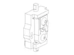
Instruction Sheet
PIDG* Terminal
408-10266
Crimping Die
2063361-1
27 Jan 09
Rev A
2. Loosen the set screw in the yoke.
Moving Die
3. Insert the shank of the nest into the yoke and
tighten the set screw.
4. Extend the ram until the set screw is visible.
5. Loosen the set screw in the ram.
Color-Code
6. Insert the shank of the indenter into the ram and
tighten the set screw.
7. Return the ram to the down position.
8. Pivot the latch arm and yoke toward each other
until the locking flange secures the latch arm to the
yoke.
2.2. Die Removal
Stationary Die
Locator
1. Pivot the latch arm away from the yoke to open
the head.
2. Loosen the set screw in the yoke and remove
the nest.
Figure 1
3. Raise the ram to “full–up” position.
1. INTRODUCTION
(Figure 1)
This instruction sheet provides application
instructions, maintenance, and inspection procedures
for PIDG Terminal Crimping Die 2063361–1 used in
Battery Tool 1901343–[ ]. This die will crimp PIDG
Terminals with a wire size range of 12–10 AWG.
Basic instructions on the use of this die, die
adjustments, wire preparation, etc. are provided in
Section 2, INSTRUCTIONS.
Section 3, MAINTENANCE and INSPECTION
PROCEDURES enables you to establish and
maintain a die certification program.
The die is coated with oil to prevent rust and
corrosion. With this oil from the dies, particularly from
the crimping area. Instructions for the Battery Tool
1901343–[ ] are found in Instruction Sheet
408–10070.
NOTE
2.3. Wire Stripping and Crimping Procedure
A. Wire Stripping
Strip the wires to the dimensions provided in Figure 2.
NOTE
Refer to Paragraph 2.4 for die insulation crimp
adjustment.
i
B. Crimping Procedure
DANGER
Avoid personal injury. When operation the tool,
exercise caution while holding terminals or wire
near the crimping area.
Dimensions in this instruction sheet are in
millimeters [with inches in brackets]. Figures and
i
4. Loosen the set screw in the ram and remove the
indenter.
illustrations are for reference only and are not
drawn to scale.
2. Place the terminal in the stationary die as shown
in Figure 3.
2. INSTRUCTIONS
NOTE
2.1. Die Insertion
2009 Tyco Electronics Corporation, Harrisburg, PA
All International Rights Reserved
Dies will not accommodate terminals with tongue
widths exceeding 11.91 mm [.469 in.].
1. Pivot the latch arm away from the yoke to open
the crimping head.
E
1. Select the proper terminal for the wire to be
crimped.
i
TOOLING ASSISTANCE CENTER 1-800-722-1111
This controlled document is subject to change.
PRODUCT INFORMATION 1-800-522-6752
For latest revision and Regional Customer Service,
TE logo and Tyco Electronics are trademarks.
*Trademark. Other products, logos, and company names used are the property of their respective owners.
visit our website at www.tycoelectronics.com
1 of 6
LOC B
�408-10266
PIDG Terminal Crimping Die 2063361-1
PIDG Terminal and Splice and
Finished Crimp
PLASTI-GRIP* Terminal
A
C
B
A
C
B
Crimp Dot
Code
A" Equals Strip Length
DIE ASSEMBLY
B" Equals Wire Barrel
C" Equals Insulation Barrel
WIRE SIZE (AWG)
COLOR
RANGE
CODE
2063361-1
12-10
WIRE STRIP LENGTH
CRIMP
DOT
TERMINAL
CODE
Yellow
1
SPLICE
MIN
MAX
MIN
MAX
7.95 [.313]
8.74 [.344]
8.74 [.344]
9.52 [.375]
PIDG Insulation Restricting Nylon Terminal
A
A" Equals Strip Length
C
Crimp Dot
B
B" Equals Wire Barrel
Insulation
COLOR
SIZE (AWG)
12
INSULATION
CODE
DIAMETER RANGE
TERMINAL
DOT
INSULATION
CODE
COLOR STRIPE
WIRE STRIP LENGTH
MIN
MAX
9 52 [[.375]
9.52
375]
10 31 [.406]
10.31
[ 406]
Yellow
Yellow
10
CRIMP
2.41-5.08 [.095-.200]
2063361 1
2063361-1
Code
3 Equally Spaced Color Stripes
C" Equals Insulation Barrel
WIRE
DIE ASSEMBLY
Finished Crimp
1
3.02-5.08 [.119-.200]
Brown
Figure 2
3. Jog the ram by pulsing the trigger until the
moving die retains, but does not deform the
terminal.
See Figure 1. This is the No. 3 or loose position.
(The insulation crimper screw must be loosened to
make this adjustment.)
4. Insert a stripped wire into the terminal until the
wire butts against the locator.
3. Turn the insulation crimper screw enough to
hold the die firmly in place. The insulation crimper
screw will be tightened after completing steps 5
and 6.
NOTE
Do not turn or twist the wire or terminal during
insertion.
4. Insert the unstripped wire into ONLY the
insulation barrel position of the terminal.
i
5. Hold the wire in place while activating the tool to
complete the crimp.
6. The ram should automatically retract when the
crimping cycle is complete. The terminal can be
removed after the ram has retracted.
2.4. Insulation Crimp Adjustment
1. The insulation crimping section of the moving
die has three crimp positions: 1–Tight, 2–Medium,
and 3–Loose.
2. Turn both insulation crimp adjustment spacers
so that they fit into the notch in the side of the die.
2 of 6
5. Make a test crimp (refer to Paragraph 2.3.B for
crimping procedure). Close the die on the terminal
and hold the die in the bottomed position. Tighten
the insulation crimper screw while the dies are
bottomed, then complete the crimping cycle.
6. Remove the terminal from the dies, and check
the insulation grip as follows: bend the wire back
and force once. The terminal sleeve should retain
the grip on the wire insulation.
7. If the wire pulls out, use the following procedure
to set the insulation crimp adjustment to the next
tighter position:
(a) First, loosen the insulation crimper screw.
Tyco Electronics Corporation
Rev A
�408-10266
PIDG Terminal Crimping Die 2063361-1
NOTE: To locate PIDG
(b) Then, turn the lower insulation adjustment
spacer 90° so that it fits between the insulation
crimper and the die. The No. 2 will appear on
the corner of the spacer.
STRATO-THERM* Terminals,
pull locator down slightly.
Terminal Barrel
Rests Against
(c) Repeat the test crimp, and adjust the die as
necessary until the desired insulation grip is
obtained.
Locator
8. With both adjustment spacers placed between
the die and the die holder, the die is set in its
tightest insulation crimping position. The No. 1 will
appear on the corner of the top spacer.
Locator
Insulation
Wire Barrel
Crimping
Crimping
Section of
Section of
Die
Die
PIDG Splice
Window Indent Slid
2.5. PLASTI-GRIP Terminal
Over and Down Into
Locator
The insulation crimping section of the moving die has
three crimp positions: 1–Tight, 2–Medium, 3–Loose.
Adjust the insulation crimp as follows:
NOTE
PLASTI-GRIP terminals feature a wire insulation
support only.
i
Locator
1. Use Position 3 for wire having a large insulation
diameter. Remove the insulation crimper screw.
Turn both insulation adjustment spacers so that
they fit into the notch in the side of the die.
DIAMOND GRIP*
Window Indent Slid
Splice
Over Locator
2. Use Position 2 for wire having a medium
insulation diameter. Remove the insulation crimper
screw. Turn the lower insulation adjustment spacer
90° so that it fits between the moving die and the
die holder. No. 2 will appear on the corner of the
spacer nearest the color code dot.
3. Use Position 1 for wire having a small insulation
diameter. Turn both insulation adjustment spacers
so that they will fit between the moving die and the
die holder. No. 1 will appear on the corner of the
top spacer nearest the color dot code.
CAUTION
Locator
Wire Barrel Against
Locator
Figure 3
Damaged product should not be used. If a
damaged product is evident, it should be cut from
!
the wire and replaced with a new one. Do NOT
reterminate terminals.
3. MAINTENANCE AND INSPECTION PROCEDURE
Tyco Electronics recommends that a maintenance
inspection program be performed periodically. This is
necessary to ensure that continued use of the dies
will result in the same dependable and uniform
terminations for which the dies were designed.
Rev
A
Tyco Electronics recommends an initial frequency of
inspection of once a month. This frequency may be
adjusted to suit requirements through experience.
The frequency of an inspection is dependent upon:
S The care, amount of use, and handling of the
dies
S The type and size of the products applied
S The degree of operator skill
S The presence of abnormal amounts of dust and
dirt
S User–established standards
Tyco Electronics Corporation
3 of 6
�408-10266
PIDG Terminal Crimping Die 2063361-1
All Tyco Electronics dies are thoroughly inspected
before being shipped from the factory, however, since
there is a possibility of die damage during shipment,
Tyco Electronics recommends that new dies be
inspected in accordance with Section 3 when
received in your plant.
Pitted
Chipped Edge
3.1. Cleaning
Do not allow deposits of dirt, grease, and foreign
matter to accumulate in the die closure area and on
the bottoming surfaces of the dies. These deposits
may prevent the dies from bottoming fully and may
also cause excessive wear in the die closure
surfaces, thereby affecting the quality of the crimp.
The dies should be wiped clean frequently with a
clean, soft cloth.
3.2. Visual Inspection
Visually inspect the die closure surfaces for broken,
chipped, or pitted conditions. Although dies may gage
within permissible limits, worn or damaged die closure
surfaces are objectionable and can affect the quality
of the crimp. Examples of possible damaged die
surfaces are shown in Figure 4.
3.3. Die Closure Inspection
Every Tyco Electronics die set is inspected and tested
for proper die closure before being shipped from the
factory. An inspection should, however, be performed
periodically to measure the die closure.
The die closure inspection is accomplished using the
GO, NO–GO plug gages. A suggested plug gage
design of the GO, NO–GO dimensions of the plug
gage members are provided in Figure 5.
The following procedure is recommended for
measuring the die closures:
2. Turn both insulation adjustment spacers of the
moving die so that they fit into the notch in the side
of the die. See Figure 1. The die is now set in the
No. 3 or loose position. This will provide access to
the wire barrel dies for plug gaging.
4 of 6
Figure 4
4. Some dies need to be removed from the hand
tool to gage the wire barrel dies. The position of
the locator and the insulation die prevent gaging
the wire barrel in the tool. Remove the complete
die assembly and rotate the locator 180°. This will
allow access to the wire barrel die. The complete
die can then be placed in a vise with light pressure
for gaging.
5. With the wire barrel dies bottomed, check the
wire barrel crimp die closure using the proper plug
gage. Hold the gage in a straight alignment with
the die closure and carefully try to insert, without
forcing the GO member, and then the NO–GO
member. See Figure 6, Detail A. The GO member
must pass completely through the insulation and
wire barrel crimp die closures.
6. The NO–GO member may enter partially, but
must not pass completely through the wire barrel
crimp die closure. See Figure 6, Detail A.
7. Remove the moving die from the tool die holder.
8. Reposition the insulation adjustment spacers in
the No. 1 position. Refer to Paragraph 2.4 for
insulation crimp position adjustment procedures.
9. Insert the moving die into the tool die holder.
1. Remove traces of oil or dirt from the die
crimping areas, and plug gage members.
3. Insert both dies in the tool die holders.
Broken Corner
10. With the wire barrel dies bottomed, check the
insulation crimp die closure using the proper plug
gage in the same manner as steps 6 and 7. See
Figure 6, Detail B.
11. If both the wire barrel and insulation die
closures meet the GO, NO–GO gage conditions,
the dies may be considered dimensionally correct.
12. If you find that the crimp die closures do not
conform with the GO, NO–GO gage conditions,
contact your local Tyco Electronics Representative.
Tyco Electronics Corporation
Rev A
�408-10266
PIDG Terminal Crimping Die 2063361-1
Wire Barrel Die
Closure Configurations
NO-GO Dimension
GO Dimension
50.8 [2.000] Min. Typ
Insulation Barrel Die
Closure Configurations
GO Dimension
NO-GO Dimension
W"
6.35 [.250] Typ
WIRE BARREL CRIMP CHAMBER
DIE SET
2063361-1
GO
INSULATION BARREL CRIMP CHAMBER
NO-GO
GO
NO-GO
4.293-4.300
4.442-4.445
1.626-1.633
2.131-2.134
[.1690-.1693]
[.1749-.1750]
[.0640-.0643]
[.0839-.0840]
WIDTH (W)
4.34 [.171] Max.
Figure 5
Inspection of Wire Barrel Crimping Dies (Detail A)
Inspection of Insulation Barrel Crimping Dies (Detail B)
Wire Barrel Dies
Bottomed, but Not
Under Pressure
Adjustment Spacers
Adjustment Spacers
in No. 3 Position
in No. 1 Position
Wire Barrel Gage Must Pass
Through the Insulation Crimp
Die Closure to Enter Wire
Insulation
Barrel Crimp Die Closure
Dies
GO" Gage Must Pass Completely Through Die Closure
GO" Gage Must Pass Completely Through Die Closure
NO-GO" Gage May Enter Partially, but Must
NO-GO" Gage May Enter Partially, but Must
Not Pass Completely Through the Die Closure
Not Pass Completely Through the Die Closure
Figure 6
Rev A
Tyco Electronics Corporation
5 of 6
�408-10266
PIDG Terminal Crimping Die 2063361-1
4. REPLACEMENT PARTS
A complete inventory of customer–replaceable parts
for each die set assembly should be stocked and
controlled to prevent lost time when replacement of
parts is necessary. See Figure 7. Order replacement
parts through your local Tyco Electronics
Representative, or call 1–800–526–5142, or send a
facsimile of your purchase order to 1–717–986–7605,
or write to:
CUSTOMER SERVICE (38–35)
TYCO ELECTRONICS CORPORATION
P.O. BOX 3608
HARRISBURG PA 17105–360
Tools and dies may also be returned to evaluation and
repair. For repair service, contact a Tyco Electronics
Representative at 1–800–526–5136.
5. REVISION SUMMARY
S Initial release of document
6
13
10
5
4
9
12
1
11
2
14
7
3
8
ITEM
NO.
DESCRIPTION
PART NUMBER
QTY
1
ANVIL, Insulation
1-45932-9
1
2
BARREL NUT
2031532-1
1
3
INDENTER, 12-10, PIDG
2063362-1
1
4
INDENTER, Insulation
306030-6
1
5
LOCATOR
3-304052-0
1
6
NEST, 12-10 PIDG
2063363-1
1
7
PIN, Coiled, Spring, Medium
21949-1
2
8
PLATE, Alignment
125152-3
1
9
SPACER, Insulation Adjustment
1-306027-0
1
10
SPACER, Insulation Adjustment
306027-9
1
11
SPACER, Locator, Housing
2-305832-9
1
12
SPRING, Compression
7-59683-4
2
13
SCREW, Btn Skt HD Cap 10-32 x [.625]
2-21002-8
1
14
SCREW, Btn Skt HD Cap 8-32 x [.625]
2-21002-3
1
Figure 7
6 of 6
Tyco Electronics Corporation
Rev
A
�