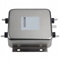
Catalog: 1654001
Issue Date: 06.2011
Corcom Product Guide
Multipurpose Power Line RFI Filter for Emission Control
V and W Series
UL Recognized
CSA Certified
VDE Approved1
VV1 / VW1
VV6 / VW6
Both the V and W series are effective to control
emissions in equipment using SCR and T2L circuits
for compliance with FCC Part 15, Subpart J and
EN55022, Level A, down to 150kHz
V Series
• Offers an N = 3 (“T”) Line to Ground impedance to
common mode and an N = 5 “Dbl. Pi”) impedance
for Line to Line differential mode interference
• Designed for susceptibility use when equipment
impedance at RF frequencies is low
W Series
• Offers an N = 4 (“Dbl. L”) Line to Ground
impedance for common mode and an N=5 (“Dbl.
Pi”) impedance for Line to Line differential mode
interference
• Designed for use when equipment impedance at
RF frequencies is high
• Two stage construction provides excellent
suppression at high frequencies
Ordering Information
20 V V 6
Specifications
Maximum leakage current each Line to Ground:
@ 120 VAC 60 Hz:
.5 mA
@250 VAC 50 Hz:
.82 mA
Hipot rating (one minute):
Line to Ground:
Line to Line:
Rated Voltage (max):
250 VAC
Operating Frequency:
50/60 Hz
Rated Current:
3 to 20A*
Operating Ambient Temperature Range
(at rated current Ir):
-10°C to +40°C
In an ambient temperature (Ta) higher than +40°C
the maximum operating current (Io) is calculated as
follows: Io = Ir (85-Ta)/45
Electrical Schematics
V Series
LINE
(load side)
LOAD
W Series (3, 6 & 10A)
LINE
Input / Output Style
1 – .250 [6.3] spade terminals
6 – Threaded bolt
7 – IEC inlet* (line side)
.250 [6.3] spade terminals
2250 VDC
1450 VDC
LOAD
W Series (20A)
LINE
LOAD
V or W Series
Leakage current designation
V – Standard
Current Rating
3, 6, 10 or 20A
*IEC 60320-1 C20 inlet mates with C19 connector
120VW7, 20A model tested by Underwriters Laboratories
to US and Canadian requirements and is
VDE approved at 16A, 250VAC
86
Dimensions are in inches and millimeters unless otherwise specified. Values in italics
are metric equivalents. Dimensions are shown for reference purposes only.
Specifications subject to change.
For email, phone or live chat, please go to
te.com/help
corcom.com
�Catalog: 1654001
Issue Date: 06.2011
Corcom Product Guide
Multipurpose Power Line RFI Filter for Emission Control (continued)
Case Styles (continued)
VW7
V and W Series
Threaded inserts
Available Part Numbers
3VV1
6VV1
10VV1
20VV1
20VV6
3VW1
3VW1
10VW1
20VW1
20VW6
20VW7*
2.25
57.15
B
B
Recommended Panel Cutout
.157
3.98 Dia.
1.22
30.99
C
2.30
58.42
1.60
40.46
C
L
.75
19.05
Mounting Plane
.219
R
5.56
V1 / W1 (20A)
2.12
53.85
Case Dimensions
Part No.
E D B
2.00
50.8
A
C
V6 / W6
E D B
A
B
C
6VV1, 6VW1
10VV1, 10VW1
20VV1, 20VW1
20VV6, 20VW6
20VW7
3VV1, 3VW1
C
A
RFI Power Line Filters
5.33 ± .025
135.38 ± .635
Case Styles
V1 / W1 (3, 6 & 10A)
D
E
A
1
.047 ± .010
1.19 ± .25
D
E
2.00
50.8
A
C
*20VW7, 20A model tested by Underwriters Laboratories
to US and Canadian requirements and is
VDE approved at 16A, 250VAC
87
Dimensions are in inches and millimeters unless otherwise specified. Values in italics
are metric equivalents. Dimensions are shown for reference purposes only.
Specifications subject to change.
For email, phone or live chat, please go to
te.com/help
corcom.com
�Catalog: 1654001
Issue Date: 06.2011
Corcom Product Guide
Multipurpose Power Line RFI Filter for Emission Control (continued)
V and W Series
Performance Data
Typical Insertion Loss
Measured in closed 50 Ohm system
Common Mode / Asymmetrical (L-G)
Differential Mode / Symmetrical (L-L)
3VV
6VV
10VV
20VV
db
100
db
100
db
100
db
100
90
90
90
90
80
80
80
80
70
70
70
70
60
60
60
60
50
50
50
50
40
40
40
40
30
30
30
30
20
20
20
20
10
10
10
0
0.1
1
0
10
30
Frequency in MHz
0.1
1
10
30
Frequency in MHz
0
10
0.1
1
0
10
30
Frequency in MHz
0.1
3VW
6VW
10VW
20VW
db
100
db
100
db
100
db
100
90
90
90
90
80
80
80
80
70
70
70
70
60
60
60
60
50
50
50
50
40
40
40
40
30
30
30
30
20
20
20
20
10
10
10
0
0
0.1
1
10
30
Frequency in MHz
0.1
1
10
30
Frequency in MHz
0
1
10
30
Frequency in MHz
1
10
30
Frequency in MHz
10
0.1
1
0
10
30
Frequency in MHz
0.1
Minimum Insertion Loss
Measured in closed 50 Ohm system
Common Mode / Asymmetrical (Line to Ground)
Differential Mode / Symmetrical (Line to Line)
88
Dimensions are in inches and millimeters unless otherwise specified. Values in italics
are metric equivalents. Dimensions are shown for reference purposes only.
Specifications subject to change.
For email, phone or live chat, please go to
te.com/help
corcom.com
�
很抱歉,暂时无法提供与“20VV1”相匹配的价格&库存,您可以联系我们找货
免费人工找货