Moulded Chip Inductor 18:12
Type 3613C Series
Type 3613C Series
Characteristics Style Opening
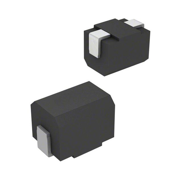
Specially developed for automatic
mounting applications, this exciting
range of chip inductors are ferrite
based and sealed in a thermoset
plastic body. They employ solder
coated copper terminations with
barrier layer. Customers can therefore
expect consistent quality, performance
and reliability. Its smooth top surface
makes it particularly well suited to pick
and place equipments.
Truly the last word in 1812 chip
inductors.
Key Features
■
High Reliability
■
Small Versatile Size 3.2 x 4.5 mm
■
Temperature Range
-30°C to +100°C
■
Supplied in Standard
Carrier Tape
■
Suitable for Dip and Wave
Solder
■
Insulation 1000M R min
■
Available from Stock
Nominal
Inductance
(µH)
0.10
0.12
0.15
0.18
0.22
0.27
0.33
0.39
0.47
0.56
0.68
0.82
1.0
1.2
1.5
1.8
2.2
2.7
3.3
3.9
4.7
5.6
6.8
8.2
10.0
12.0
15.0
18.0
22.0
27.0
33.0
39.0
47.0
56.0
68.0
82.0
100
120
150
180
220
270
330
390
470
560
680
820
1000
Value
Coding
Marking
R10M
R12M
R15M
R18M
R22M
R27M
R33M
R39M
R47M
R56M
R68M
R82M
1R0K
1R2K
1R5K
1R8K
2R2K
2R7K
3R3K
3R9K
4R7K
5R6K
6R8K
8R2K
100K
120K
150K
180K
22OK
270K
330K
390K
470K
560K
680K
820K
101K
121K
151K
181K
221K
271K
331K
391K
471K
561K
681K
821K
102K
Inductance
Tolerance
(±%)
±20%
±20%
±20%
±20%
±20%
±20%
±20%
±20%
±20%
±20%
±20%
±20%
±10%
±10%
±10%
±10%
±10%
±10%
±10%
±10%
±10%
±10%
±10%
±10%
±10%
±10%
±10%
±10%
±10%
±10%
±10%
±10%
±10%
±10%
±10%
±10%
±10%
±10%
±10%
±10%
±10%
±10%
±10%
±10%
±10%
±10%
±10%
±10%
±10%
Q
(min)
35
35
35
35
40
40
40
40
40
40
40
40
50
50
50
50
50
50
50
50
50
50
50
50
50
50
50
50
50
50
50
50
50
50
50
50
40
40
40
40
40
40
40
40
40
30
30
30
20
Self Resonant
DC
Frequency
Resistance
(MHz) (min) (ohms max)
300
0.18
280
0.20
250
0.22
220
0.24
200
0.25
180
0.26
165
0.28
150
0.30
145
0.32
140
0.36
135
0.40
130
0.45
100
0.50
80
0.55
70
0.60
60
0.65
55
0.70
50
0.75
45
0.80
40
0.90
35
1.00
33
1.10
27
1.20
25
1.40
20
1.60
18
2.00
17
2.50
15
2.80
13
3.20
12
3.60
11
4.00
10
4.50
10
5.00
9.0
5.50
9.0
6.00
8.0
7.00
8.0
8.00
6.0
8.00
5.0
9.00
5.0
9.50
4.0
10.0
4.0
12.0
3.5
14.0
3.0
18.0
3.0
26.0
3.0
30.0
3.0
30.0
2.5
35.0
2.5
40.0
Allowance
DC
(mA)
800
770
730
700
665
635
605
575
545
520
500
475
450
430
410
390
380
370
355
330
315
300
285
270
250
225
200
190
180
170
160
150
140
135
130
120
110
110
105
102
100
92
85
80
62
50
50
30
30
Measuring
Frequency
(MHz)
25.2
25.2
25.2
25.2
25.2
25.2
25.2
25.2
25.2
25.2
25.2
25.2
7.96
7.96
7.96
7.96
7.96
7.96
7.96
7.96
7.96
7.96
7.96
7.96
2.52
2.52
2.52
2.52
2.52
2.52
2.52
2.52
2.52
2.52
2.52
2.52
0.796
0.796
0.796
0.796
0.796
0.796
0.796
0.796
0.796
0.796
0.796
0.796
0.252
5% Tolerance available on selected value ranges. Please enquire
Characteristics Environmental
Insulation:
Temperature Range:
Humidity Load life:
Vibration (see test method):
Literature No. 1773143
Issued: 01-07
Dimensions are shown for
reference purposes only.
Dimensions are in millimetres
unless otherwise specified.
1000 M ohms
-30°C to +100°C
∆L/L within ±10%
∆L/L within ±5%
Specifications subject to
change.
www.tycoelectronics.com
passives.tycoelectronics.com
�Moulded Chip Inductor 18:12
Type 3613C Series
Dimensions
Test Methods
Item
Standard
Test Method
DC Superposition
Characteristics
∆L/L Within -10%
When the allowable current was applied, the inductance was measured
with a YHP 4262A and compared with the initial value.
Temperature
Rise
Within 20°C
When the allowable current was applied, the amount of temperature rise
was measured by the change in resistance.
Temperature
Rise
∆L/L Within ± 5%
Measurements were taken in a temperature range of -25°C to 85°C and
the value at +20°C was used as the standard value.
Overcurrent
Test
No smoke and no fire
Twice the allowable current was applied for a period of five minutes.
Insulation
Resistance
Not less than 1000 M
0.3mm diameter copper wires were wound around the coils three times and
measurements were taken after 250VDC was applied between the wire and the
terminals for a period of 1 minute.
Tensile
Strength Test
No separation from substrate
After the inductors were soldered to substrates, a force of 1.0kg was applied in both
the x and y directions for a period of 5 seconds.
Stress Test
No breakage
After the inductors were mounted on substrates, 1-mins. 10-55-10 cycle per seconds
sweeps 1.5mm stroke vibrations were applied for 2 hrs. each in the X, Y and Z directions.
Drop Test
No pronounced abnormality in
appearance
The inductors were dropped 10 times from a height of 1.0 metre onto a concrete floor.
Vibration Test
∆L/L Within ± 10%
Q Not less than 30
After the inductors were mounted on substrates, 1-mins. 10-55-10 cycle per seconds
sweeps 1.5mm stroke vibrations were applied for 2 hours each in the X, Y and Z
directions
Humidity Resistance
Load Test
∆L/L Within ± 10%
Q Not less than 30
Measurements were taken after the allowable current was applied while the inductors
were stored at 60°C ± 2°C in 90 to 95% RH for a period of 500 hours.
Low Temperature
Resistance Test
∆L/L Within ± 10%
Q Not less than 30
Measurements were taken after the inductors were stored at -40°C ± 2°C for period
1000 hours
Temperature
Cycle Test
∆L/L Within ± 10%
Q Not less than 30
Measurements were taken after the inductors were stored for 30 minutes, during which
they were subjected to 20 temperature cycles of between -25°C and +85°C.
High Temperature
Resistance Load Test
∆L/L Within ± 10%
Q Not less than 30
Measurements were taken after the allowable was applied while the inductors were stored
at 85°C for a period of 1000 hours.
Test Notes
The measuring method for the test data given overpage are as follows:
Inductance: Direct reading from Q-meter (equivalent to YHP 4342A, jig used)
Q: Direct reading from Q-meter (equivalent to YHP 4342A, jig used)
Self resonant frequency: Grid Dipo Meter (equivalent to Measurement M159)
DC resistance: Wheatstone bridge (equivalent to YEW 2755)
Unless otherwise specified, the temperature is 20°C ± 5°C and the humidity is 65% ± 20%
How to Order
3613C
1R5
K
Common Part
Inductance
Tolerance
3613C - 18:12
Inductor
Value Code
(see table)
J - ±5%
K - ±10%
M - 20%
Literature No. 1773143
Issued: 01-07
Dimensions are shown for
reference purposes only.
Dimensions are in millimetres
unless otherwise specified.
Specifications subject to
change.
www.tycoelectronics.com
passives.tycoelectronics.com
�
很抱歉,暂时无法提供与“3613C101K”相匹配的价格&库存,您可以联系我们找货
免费人工找货- 国内价格 香港价格
- 500+2.83983500+0.36424
- 1000+2.677701000+0.34345
- 1500+2.587221500+0.33184
- 2500+2.477622500+0.31778
- 3500+2.408033500+0.30886
- 5000+2.336465000+0.29968
- 国内价格
- 500+3.99003
- 1000+2.97077
- 10000+2.85890
- 20000+2.70974
- 50000+2.48600
- 国内价格
- 500+3.99003
- 1000+2.97077
- 10000+2.85890
- 20000+2.70974
- 50000+2.48600
- 国内价格
- 1+5.32440
- 10+5.21640
- 30+5.15160