Instruction Sheet
408-- 1634
Die Assemblies 45218, 45221,
69303- 2, and 69820
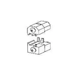
Insert Anvil
(Moving Die)
NOTE
Insert Indenter
(Stationary Die)
Screw
Dimensions on this instruction sheet are in
millimeters [with inches in brackets]. Figures are
not drawn to scale.
Reasons for reissue of this instruction sheet are
provided in Section 8, REVISION SUMMARY.
2. DESCRIPTION
Ejector
SPLICE
The die assembly consist of an insert indenter
(moving die) and an insert anvil (stationary die).
The stationary die is identified by the chamfered
corners. The stationary die is marked with the die
assembly part number, wire size (AWG), and splice
type. When mated, the die assembly forms one
crimping chamber. Each die is secured in the tool by
a single screw.
3. DIE INSTALLATION
Locator (Except Die
Assembly 69820)
DIE ASSEMBLY
PART
NUMBER
MARKING
SIZE
MINIMUM OPENING
DIAMETER
45218
18--16
ECV--ECN
22--14
—
45221
18--10
ECV--ECN
22--10
—
69303--2
18--16 EC
22--16
6.73 mm [.265 in.]
18--16 ECVG
22--16
6.48 mm [.255 in.]
69820
i
04 JAN 10 Rev C
Figure 1
Die Assemblies 45218, 45221, 69303--2 (shown in
Figure 1), and 69820 are used with the following tools
to crimp vinyl closed--end splices and nylon
closed--end splices onto solid and stranded wire sizes
22 through 10 AWG. For specific information
concerning the tools, refer to instruction sheet
(408--series) or customer manual (409--series) listed.
Straight Action Hand Tool 69710--1
626 Pneumatic Tooling Assembly
189721--1 or 189722--1
Fitted with Straight Action Crimper
217200--1 or 189721--2
626 Pneumatic Tooling Assembly
189722--2
Fitted with C--Head Pneumatic Adapter
318161--1
4. CRIMPING PROCEDURE
NOTE
i
1. INTRODUCTION
TOOL
Install the die assembly onto the tool according to the
instructions supplied with the tool. If using the
pneumatic tooling assembly, follow the instructions
supplied with the applicable crimper or adapter.
REFERENCE
DOCUMENT
408--2095
409--5862
408--4195
409--5862
408--4190
Die Assembly 69820 requires an insulation crimp
adjustment. Before crimping any splices, refer to
Section 5 for proper adjustment.
1. Select proper wire combinations as stated in the
applicable wire combination chart specified in
Figure 2. Strip wires to length indicated in Figure 2.
Do not use wires with nicked or missing strands.
NOTE
i
If conductors are twisted together to form a tight
bundle before inserting them into the splice, the
strip length must be maintained after twisting.
2. Insert the splice, wire barrel first, into the ejector
of the stationary die until splice bottoms. For nylon
splices, the shoulder must rest against the ejector;
for vinyl splices, the end of the wire barrel of must
rest against the locator. Die Assembly 69820 does
not have a locator; therefore, the wire barrel must
rest against the wire barrel section of the die. See
Figure 3. Close dies until splice is held in place.
3. Insert stripped wires into splice wire barrel until
conductors bottom. See Figure 3.
DANGER
Read these instructions and referenced documents
before crimping any splices.
TOOLING ASSISTANCE CENTER 1-- 800-- 722-- 1111
E2010 Tyco Electronics Corporation, Harrisburg, PA
PRODUCT INFORMATION 1-- 800-- 522-- 6752
All International Rights Reserved
TE logo and Tyco Electronics are trademarks.
*Trademark. Other products, logos, and company names used are the property of their respective owners.
Always keep fingers clear of dies during tool
operation.
This controlled document is subject to change.
For latest revision and Regional Customer Service,
visit our website at www.tycoelectronics.com
1 of 6
LOC B
�408- 1634
Die Assemblies 45218, 45221, 69303- 2, and 69820
Nylon Splices
Shoulder Resting
Against Die Ejector
Wire Strip Length (Ref)
Typical Closed-- End
Splice
SPLICE
SIZE
22 16
22--16
TYPE
ECV
VS
22--14
ECN
INSTRUCTION SHEET FOR
WIRE COMBINATIONS
WIRE STRIP
LENGTH
408--1395
(6.73 [.265] Splice
Min Opening Diameter)
7.94--8.73
[.312--.344]
408--2228
(6.48 [.255] Splice
Min Opening Diameter)
10.32--11.90
[.406--.469]
408--1394
408--1271
(Transparent Splice)
End of Wire Barrel
Resting Against
Die Locator
8.33--9.13
[[.328--.359]
328-- 359]
408--8806
(Black Splice)
ECV
408--1002
14.29--15.87
[.562--.625]
ECN
408--1021
10.72--11.51
[.422--.453]
22 10
22--10
Vinyl Splice
Nylon or Vinyl Splice in Die Assembly 69820
Front of Wire Barrel
Resting Against Wire
Barrel Section of Die
Figure 2
4. Hold the wires in place, and actuate the tooling
through a complete cycle.
5. Allow the dies to open FULLY, then remove the
crimped splice (if splice is difficult to remove, twist
splice one--quarter turn). Inspect the crimped splice
according to Figure 4.
NOTE
i
For detailed information on inspection
requirements, refer to Application Specification
114--2147 for nylon splices and 114--2149 for
vinyl splices.
Figure 3
5. INSULATION CRIMP ADJUSTMENT
Crimp Centered on Wire Barrel (May Be
Off Center But Not Off End of Wire Barrel)
(For Die Assembly 69820 Only)
The moving die has three insulation adjustment
settings to adjust the wire insulation grip: 1—Tight,
2—Medium, and 3—Loose. To determine the proper
insulation crimp setting, proceed as follows (refer to
Figure 5):
1. Remove the moving die from the tool.
2. Loosen, but do not remove, the die screw. Set
the insulation crimp adjustment to Setting 1 (as
described in Figure 5).
2 of 6
Properly Stripped Wires
Bottomed in Splice
Correct Wire Size
Combination
No Nicked or Missing
Wire Strands
Tyco Electronics Corporation
Figure 4
Rev C
�408- 1634
Die Assemblies 45218, 45221, 69303- 2, and 69820
Setting 1—Tight
Turn both insulation adjustment spacers until the “1” (stamped on
the die) is visible at the beveled corner of the spacers. When
installed into the tool, the L-- shaped edge of the spacers will fit
between the die and the tool.
Setting 2—Medium
Turn the insulation adjustment spacer closest to the die until the
“2” (stamped on the die) is visible at the beveled corner of the
spacer. When installed into the tool, the L-- shaped edge of the
spacer will fit between the die and the tool.
Setting 3—Loose
Turn both insulation adjustment spacers until the “3” (stamped on
the die) is visible at the beveled corner of the spacers. The
L-- shaped edge of the spacer will fit into the notch in the side of
the die.
Die Assembly 69820 Shown
Insulation
Adjustment Spacers
Setting 3
Shown
Screw Loosened
3. Tighten the die screw. Install die into tool.
4. Perform a test crimp following the steps in
Section 4, and inspect the splice insulation. If the
crimp cuts into, or otherwise damages, the
insulation, start with Step 1 and set the insulation
crimp adjustment to the next setting (Setting 2, as
described in Figure 5). Perform another test crimp.
If the crimp does not meet requirements, set the
adjustment to Setting 3. If the crimp meets
requirements, the adjustment is properly set.
6. MAINTENANCE AND INSPECTION
6.1. Daily Maintenance
It is recommended that each operator of the die
assembly be made aware of, and responsible for, the
following steps of daily maintenance:
1. Remove all foreign particles from the dies with a
clean, soft brush, or a clean, soft, lint--free cloth.
Do not use objects that could damage the dies.
Rev C
3. Make certain that the dies are protected with a
thin coat of any good SAE 20 motor oil. DO NOT
oil excessively.
4. When dies are not in use, mate them and store
them in a clean, dry area.
6.2. Periodic Inspection
Regular inspections should be performed by quality
control personnel with a record of scheduled
inspection remaining with the die assembly or
supplied to personnel responsible for them. Though
recommendations call for at least one inspection per
month, inspection frequency should be based upon
amount of use, working conditions, operator training
and skill, and established company standards. The
inspections should be performed in the following
sequence.
1. Remove all lubrication and accumulated film by
immersing the dies in a suitable commercial
degreaser that will not affect paint or plastic
material.
2. Make sure that screws, retaining rings, and die
components are in place.
Figure 5
SAE is a trademark of SAE International Corporation.
2. Make sure that the proper screws and retaining
rings are in place and are secured. Check die
alignment and tighten screws (twice daily is
recommended for production use).
3. Check all bearing surfaces for wear. Replace
worn components.
4. Inspect the crimping chamber for flattened,
chipped, cracked, worn, or broken areas. If
damage is evident, the dies must be repaired
before returning them to service.
6.3. Gaging the Crimping Chamber
This inspection requires the use of plug gages
conforming to the dimensions provided in Figure 6.
To gage the crimping chamber, proceed as follows:
1. Remove traces of oil or dirt from the crimping
chamber and plug gage.
2. For pneumatic tools, reduce air supply pressure
on tool to between 103 and 138 kPa [15 and
20 psi]. Actuate tool until dies bottom. For manual
tools, close handles until dies bottom. DO NOT
force beyond initial contact.
3. Insert GO element into the crimping chamber;
but do not force it. The GO element must pass
completely through the crimping chamber. See
Figure 7.
Tyco Electronics Corporation
3 of 6
�408- 1634
Die Assemblies 45218, 45221, 69303- 2, and 69820
Suggested Plug Gage Design for
Wire Barrel Section
GO
Dia
Inspection of Crimping Chamber
NO-- GO
Dia
25.4 [1.0]
Min Typ
GO Element
Die Closure
Configuration
GAGE ELEMENT DIAMETER
GO
NO-- GO
45218
2.3114--2.3190
[.0910--.0913]
2.4613--2.4638
[.0969--.0970]
45221
3.1242--3.1318
[.1230--.1233]
3.2741--3.2766
[.1289--.1290]
69303--2
2.6670--2.6746
[.1050--.1053]
2.8169--2.8194
[.1109--.1110]
69820
2.6670--2.6746
[.1050--.1053]
2.8169--2.8194
[.1109--.1110]
GO Dia
4. In the same manner, try to insert the NO--GO
element into the crimping chamber. The NO--GO
element may enter partially, but must not pass
completely through the length of the crimping
chamber. See Figure 7.
If the crimping chamber conforms to the gage
inspection, the dies may be considered dimensionally
correct and should be lubricated with a THIN coat of
any good SAE 20 motor oil. If the crimping chamber
does NOT conform to the gage inspection, the die
assembly must be returned for repair. See Section 7.
For additional information regarding the use of a plug
gage, refer to 408--7424.
NO-- GO Dia
W
6.35 [.250]
Min Typ
Die Closure
Configuration
GAGE ELEMENT DIAMETER
GO
NO-- GO
3.7846--3.7922
[.1490--.1493]
4.2901--4.2926
[.1689--.1690]
Figure 6
NO-- GO element may enter
partially, but must not pass
completely through the
crimping chamber.
Figure 7
Suggested Plug Gage Design for
Insulation Barrel Section
69820
NO-- GO Element
Wire barrel GO element must
pass completely through the
crimping chamber.
DIE ASSEMBLY
DIE
ASSEMBLY
Crimping
Chamber
DIMENSION
“W” WIDTH
(Max)
7.49 [.295]
7. REPLACEMENT AND REPAIR
Customer--replaceable parts are listed in Figure 8.
A complete inventory should be stocked and
controlled to prevent lost time when replacement of
parts is necessary. Order replacement parts or
additional dies through your representative, or call
1--800--526--5142, or send a facsimile of your
purchase order to 717--986--7605 or write to:
CUSTOMER SERVICE (038--035)
TYCO ELECTRONICS CORPORATION
PO BOX 3608
HARRISBURG PA 17105--3608
For customer repair service, call 1--800--526--5136.
8. REVISION SUMMARY
Revisions to this instruction sheet include:
S Updated instruction sheet to corporate
requirements
4 of 6
Tyco Electronics Corporation
Rev C
�408- 1634
Die Assemblies 45218, 45221, 69303- 2, and 69820
Die Assembly 45218
Die Assembly 45221
5
5
10
13
10
13
6
6
10
10
4
4
17
1
17
1
14
2
14
2
11
11
8
8
12
Die Assembly 69303- 2
Die Assembly 69820
6
13
4
6
7
3
1
3
1
15
2
5
14
8
8
18
14
2
4
16
9
Figure 8 (Cont’d)
Rev C
Tyco Electronics Corporation
5 of 6
�408- 1634
Die Assemblies 45218, 45221, 69303- 2, and 69820
ITEM
PART NUMBER FOR DIE ASSEMBLY
DESCRIPTION
QTY PER
ASSEMBLY
45218
45221
69303-- 2
69820
1
304993
305037
1--305927--8
2--306131--1
SCREW
1
2
304991
305036
2--306131--4
3--306131--7
SCREW
1
3
—
—
1--21046--3
1--21046--3
RING, Retaining
2
4
304995
305042
306113--2
2--306113--9
EJECTOR
1
5
304992
305035
306024--8
—
LOCATOR
1
6
45296
45315
306028--7
306960
ANVIL (Stationary Die)
1
7
—
—
—
306958
ANVIL (Stationary Die, Insulation)
1
8
2--305938--0
45314
306029--7
306961
INDENTER (Moving Die)
1
9
—
—
—
306959
INDENTER (Moving Die, Insulation)
1
10
304990
305041
—
—
FLARE PLATE, Upper
2
11
304989
305040
—
—
FLARE PLATE, Lower
1
12
—
305039
—
—
FLARE PLATE, Lower
1
13
303995
303995
9--305832--5
—
SPACER, Upper
1
14
304994
304994
9--305832--6
2--59676--3
SPACER, Lower
1
15
—
—
—
306027--6
SPACER, Insulation Adjustment
1
16
—
—
—
306027--7
SPACER, Insulation Adjustment
1
17
21041--6
21041--6
—
—
PIN, Coiled Spring
2
18
—
—
—
23911--7
WASHER, Spring
1
Figure 8 (End)
6 of 6
Tyco Electronics Corporation
Rev C
�