Instruction Sheet
Instruction Sheet
ERGOCRIMP
ERGOCRIMP
Matrize
Die
PN 539 758-2
P/N 539 758-2
0,
5
-1
1,
5
-2
,5
0,
5
-1
1,
5
-2
,5
411-18233 / Rev. A1
14 NOV 2012 UL
Seite / Page 1 of 11
ECOC EG00
LOC: AI
�Matrize
PN 539 758-2
411-18233 / Rev. A1
1
Die Set
PN 539 758-2
411-18233 / Rev. A1
Hinweise zum Inhalt
dieser Betriebsanleitung
1
Notes to the Contens of
this Manual
Diese Betriebsanleitung beschreibt die Anwendung
und Bedienung der ERGOCRIMP Matrize PN
539 758-2 für den Einsatz in der ERGOCRIMP Basis
Handzange PN 539 635-1 sowie erforderliche Wartungsmaßnahmen.
This IS describes the use and the operation of the
ERGOCRIMP Die P/N 539 758-2 for the ERGOCRIMP basis hand tool P/N 539 635-1 as well as
necessary maintenance measures.
Für Informationen, die nicht in dieser Anleitung enthalten sind sowie zur Technischen Unterstützung,
wenden Sie sich bitte direkt an:
For further information, not included in this IS , and for
technical assistance please contact:
TE Connectivity
TE Connectivity
Tyco Electronics AMP GmbH
AT-Kundendienst
Gebäude 83
Landwehrstraße 55
D-64293 Darmstadt
Germany
Telefon:
+49(0)6151-607 1518
Tyco Electronics AMP GmbH
Customer Services
Building 83
Landwehrstr. 55
D-64293 Darmstadt
Germany
Tel.:
+49(0)6151-607 1518
Seite / Page 2 of 11
�Matrize
PN 539 758-2
411-18233 / Rev. A1
2
Die Set
PN 539 758-2
411-18233 / Rev. A1
Verwendungszweck
2
Application
Mit dieser ERGOCRIMP Matrize können folgende
Crimpkontakte verarbeitet werden:
This ERGOCRIMP Die is suitable to crimp the following
crimp contacts:
Kontakttyp:
TAB 2,8 mm
TAB 2,8 mm
TAB 2,8 mm (EDS)
TAB 2,8 mm (EDS)
Contact Type:
TAB 2.8 mm
TAB 2.8 mm
TAB 2.8 mm (SWS)
TAB 2.8 mm (SWS)
PN
963 745
963 746
963 748
963 749
PN (EDS)
828 904
828 905
P/N
963 745
963 746
963 748
963 749
P/N (SWS)
828 904
828 905
HINWEIS
Die ERGOCRIMP Crimp-Handzange ist für die
Aufnahme verschiedener Crimpmatrizen ausgelegt. Kontaktieren Sie den Kundendienst bezüglich der Verfügbarkeit von
Crimpmatrizen für spezielle Anwendungen.
NOTE
The ERGOCRIMP Hand Tool has been
designed to accomodate different crimp die
sets. For availability of die sets for special
applications please contact the Field Service.
HINWEIS
Alle Abmessungen in dieser Betriebsanleitung werden in Millimeter 'mm' angegeben. Die
abgebildeten Komponenten sind nicht maßstabsgetreu dargestellt.
NOTE
Dimensions on this sheet are in millimeters
"mm".Figures and illustrations are not drawn to
scale.
HINWEIS ZUR ANWENDUNG
Kumulative traumatische Beschwerden können die Folge einer dauerhaften Anwendung
von Handzangen sein. Handzangen sind für
gelegentliche Anwendungen und geringe
Stückzahlen vorgesehen. Für den gesteigerten Bedarf bzw. für die Produktion bietet TE
eine große Auswahl entsprechender Werkzeuge.
PROPER USE GUIDELINES
Cumulative Traume Disorders can result from
a prolonged use of manually powered hand
tools. Hand tools are intended for occasional
use and low volume applications. For extended
use or production operations, TE offers a wide
selection of powered application equipment.
HINWEIS
Die Werkzeuge sind ausschließlich für den
hier beschriebenen Zweck zu verwenden!
NOTE
The tool may only be used for the described
purpose.
Matrizensatz
PN
Die assembly
Part number
Kontakt
PN
Contact
Part number
Größe (mm2)
539 758-2
963 745
963 746
963 748
963 749
0,5 - 1,0
1,5 - 2,5
0,5 - 1,0
1,5 - 2,5
Size (mm2)
Bild / Figure 1
Seite / Page 3 of 11
Leitung
Isol. ø (mm)
Wire
Insul dia (mm)
Abisolierlänge
(mm)
Strip Lenght
(mm)
1,4 - 2,0
2,1 - 2,9
1,4 - 2,1
2,2 - 3,0
4,2
5,0
4,5
5,0
�Matrize
PN 539 758-2
411-18233 / Rev. A1
3
Die Set
PN 539 758-2
411-18233 / Rev. A1
Matrizen, Ein- und Ausbau
3
Die Installation and removal
Feststehende Crimpbacke
Stationary jaws
Matrizenbefestigungsschrauben
Die
retaining
screws
Zangenrückseite
Back of Tool
Abschrägung
Chamfer
Obere Matrize
Upper die
Kontaktabstützung
Contact guide
Untere Matrize
Lower die
Bild / Figure 2
Matrizen - Einbau
Die - Installation
1. Öffnen Sie die Zangengriffe und entfernen Sie die
beiden Befestigungsschrauben aus den Crimpbacken.
1. Open the tool handles and remove the two die
retaining screws from the tool jaws.
2. Positionieren Sie die Crimper-Matrize für Drahtund Isolationscrimp in der feststehenden Crimpbacke, so daß die Abschrägungen nach außen
zeigen.
2. Move the wire and insulation crimper dies, with
the chamfers facing the front of the stationary
jaws.
3. Drehen Sie eine Matrizen-Befestigungsschraube
(M4x25) durch Backe und Matrize, ziehen Sie
aber die Schraube noch nicht fest.
3. Insert a die retention screw (M4x25) through the
jaw and die and tighten the screw so that the die
is held in place, but do not tighten the screw
completely at this point.
4. Positionieren Sie die untere Matrize in der beweglichen Crimpbacke der Handzange. Drehen Sie
eine Matrizen-Befestigungsschraube (M4x16)
durch Backe und Matrize, ziehen Sie die Schraube aber noch nicht fest.
4. Place the lower die in the moving jaw of the tool
frame. Install a die retention screw (M4x16) through
the jaw and die and tighten the screw so that the
die is held in place, but do not tighten the screw
completely at this point.
HINWEIS
Der Ratschenmechanismus der Handzange
besitzt Raststufen, die beim Schließen der
Zangengriffe sieben hörbare 'Klicks' ergeben.
Beim sechsten (6.) 'Klick' wird der Ratschenmechanismus ausgelöst (geöffnet).
NOTE
The ERGOCRIMP tool ratchet has detents
that are audible as seven "clicks" as the
handles are closed. The ratchet releases on
the sixth "click".
Seite / Page 4 of 11
�Matrize
PN 539 758-2
411-18233 / Rev. A1
Die Set
PN 539 758-2
411-18233 / Rev. A1
5. Drücken Sie die Zangengriffe langsam zusammen, so daß die Matrizen aneinandergefügt und
ausgerichtet werden. Drücken Sie die Zangengriffe bis zum fünften (5.) 'Klick' zusammen und
ziehen Sie dann die beiden Matrizen-Befestigungsschrauben fest.
5. Slowly close the tool handles, allowing the dies to
mate and/or align. Continue closing the tool handles
until the rachet makes the fifth "click," then
tighten both die retention screws until snug.
6. Befestigen Sie die Positioniereinheit auf der feststehenden Crimpbacke mit der entsprechenden
Sechskantmutter.
6. Install the locator assembly on the stationary jaw
and tighten the hex nut
7. Befestigen Sie den Kontaktpositionierer auf der
beweglichen Crimpbacke, indem Sie die
Sechskantmutter festziehen.
7. Install the contact locator on the movable jaw, and
tighten hex nut.
8. Prüfen Sie die Crimphöhen. Justieren Sie, wenn
nötig wie beschrieben unter Kap. 6.
8. Check the crimp heights. If necessary, adjust it
as described in Chap. 6.
Matrizen - Ausbau
Die - removal
1. Für den Ausbau des Matrizensatzes schließen
Sie die Zange bis der Ratschenmechanismus
auslöst und die Zangengriffe (ganz) öffnen. Lösen
und entfernen Sie die Sechskantmutter und die
beiden Matrizen-Befestigungsschrauben und
schieben Sie die Matrizen aus den Crimpbacken.
1. To remove the die assembly, close the tool
handles until the ratchet releases, and allow the
handles to open fully. Loosen and remove the die
retention screws and slide the dies out of the tool
jaws.
4 Crimpverfahren
4 Crimping procedure
HINWEIS
Die Crimp-Handzange bietet eine Einstellmöglichkeit der Crimphöhe. Die Crimphöhe
muß zu Anfang, wie nachfolgend spezifiziert
(Tabelle) und beschrieben, überprüft werden,
bevor gewünschte Kontakte und Leitungsgrößen verarbeitet werden.
NOTE
This tool is provided with a crimp adjustment
feature. Initially, the crimp height should be
verified as specified in Figure 3. Refer to
Section 5, CRIMP HEIGHT INSPECTION,
and Section 6, CRIMP HEIGHT ADJUSTMENT, to verify crimp height before using the
tool to crimp desired contacts and wire sizes.
Wählen Sie eine Leitung mit spezifizierter Größe und
Isolationsdurchmesser (Bild 1). Entfernen Sie die
Isolation um die angegebene Länge ohne die Drahtlitzen zu verbiegen oder zu beschädigen. Wählen Sie
einen passenden Kontakt, und bestimmen Sie die
korrekte Kontaktaufnahme entsprechend der Markierungen (Leitungsgröße) auf der Zange. Verfahren Sie
nun wie folgt:
Refer to the table in Figure 1 and select wire of the
specified size and insulation diameter. Strip the wire
to the length indicated in Figure 1, taking care not to
bend or to damage the wire strands. Choose a fitting
contact and identify the appropriate crimp section
according to the wire size marking on the tool. Refer
to Figure 2 and proceed as follows:
1. Halten Sie die Crimpzange so, daß die Rückseite
der Zange (Leitungsseite) zu Ihnen zeigt. Drücken
Sie die Zangengriffe zusammen und lassen Sie
die Zange vollständig öffnen.
1. Hold the tool so that the back (wire side) is facing
you. Squeeze tool handles together and allow
them to open fully.
2. Halten Sie den Kontakt im Kontaktierbereich fest
und schieben Sie ihn von der Zangenvorderseite in
die Zange.
2. Holding the contact by the mating end, insert the
contact - insulation barrel first - through the front
of the tool and into the appropriate crimp section.
Seite / Page 5 of 11
�Matrize
PN 539 758-2
411-18233 / Rev. A1
Die Set
PN 539 758-2
411-18233 / Rev. A1
3. Positionieren Sie den Kontakt so, daß sich der
Kontaktierbereich des Kontaktes auf der Seite
des Kontaktpositionierers befindet und die Crimpflanken (U-Form) des Draht- und Drahtcrimps
nach oben gerichtet sind.
3. Position the contact so that the mating end of the
contact is on the Locator side of the tool, and that
the open "U" of the wire barrels face the top of the
tool.
VORSICHT
Stellen Sie sicher, daß die beiden Crimpflanken des Drahtcrimps im Crimpbereich
gleichmäßig geführt werden. Versuchen Sie
NICHT, einen ungenau positionierten Kontakt
zu crimpen.
CAUTION
Make sure that both crimpflanks of the wire
barrel are started evenly into the crimping
section. Do NOT attempt to crimp an
improperly positioned contact.
4. Halten Sie den Kontakt in Position und drücken
Sie die Zangengriffe soweit zusammen, bis der
Ratschenmechanismus entsprechend verriegelt
und der Kontakt in der Zange gehalten wird.
Achten Sie darauf, daß Sie die Isolations- und
Drahtcrimpflanken NICHT deformieren.
4. Hold the contact in position and squeeze the tool
handles together until ratchet engages sufficiently
to hold the contact in position. Do NOT deform
insulation barrel or wire barrel.
5. Führen Sie die abisolierte Leitung in die
Drahtcrimphülse (Bild 3).
5. Insert stripped wire into contact wire barrel
(Figure 3).
Zangenvorderseite
Front of Tool
Zangenrückseite
Back of Tool
Abisolierlänge
Strip lenght
Kontakt (typ.)
Contact (Typ)
Bild / Figure 3
6. Halten Sie die Leitung in dieser Stellung und
drücken Sie die Zangengriffe zusammen, bis der
Ratschenmechanismus auslöst bzw. öffnet. Lassen Sie die Zange vollständig öffnen und entnehmen Sie den gecrimpten Kontakt.
6. Holding the wire in place, squeeze tool handles
together until ratchet releases. Allow tool handles
to open and remove crimped contact.
7. Überprüfen Sie die Crimphöhe, wie nachstehend
beschrieben. Nehmen Sie ggf. eine Einstellung
der Crimphöhe vor.
7. Check the contacts crimp height as described in
Section 5, CRIMP HEIGHT INSPECTION. If
necessary, adjust the crimp height as described
in Section 6, CRIMP HEIGHT ADJUSTMENT.
Seite / Page 6 of 11
�Matrize
PN 539 758-2
411-18233 / Rev. A1
Die Set
PN 539 758-2
411-18233 / Rev. A1
Die Spitze muß mittig
auf der Drahtcrimphülse
gegenüber der Crimpnaht
positioniert werden
Position point on center of
wire barrel opposite seam
Modifizierter Amboß
Modified anvil
Leitungsgröße
(max.)
Wire size
(max.)
Crimpbereich
(Drahtgr.ber.markg.)
Crimp section
(Wire size marking)
Crimphöhe (A)
u. Toleranz (+/-0,05)
Crimp height
dim. (A) and
Tolerance
(+/-0.05)
0,5 - 1,0 mm²
1,5 - 2,5 mm²
0,5 - 1,0 mm²
1,5 - 2,5 mm²
0,5 - 1,0 mm²
1,5 - 2,5 mm²
0,5 - 1,0 mm²
1,5 - 2,5 mm²
1,23
1,63
1,23
1,63
Bild / Figure 4
Verarbeitung der Verbinder nach Verarbeitungsspezifikation 114-18051
Processing of terminals according to application
specification 114-18051
5 Überprüfung der Crimphöhe
5 Crimp height inspection
Zur Überprüfung bzw. Messung der Crimphöhe ist ein
Mikrometer mit modifiziertem Amboß erforderlich
PN: 547 203-1.
This inspection requires the use of a micrometer with
a modified anvil. TE recommends the modified
micrometer P/N: 547 203-1.
Verfahren Sie wie folgt:
Proceed as follows:
1. Wählen Sie aus der Tabelle (Bild 4) je eine Leitung
(mit max. Größe) für die gelisteten Crimp-Größenbereiche.
1. Refer to Figure 4 and select a wire (maximum
size) for each crimp section listed.
2. Crimpen Sie einen oder mehrere Kontakte wie
zuvor beschrieben.
2. Refer to Section 4, CRIMPING PROCEDURE,
and crimp the contact(s) accordingly.
3. Messen Sie mit dem Mikrometer die Crimphöhen
der Drahtcrimphülse und Isolationscrimphülse wie
in der Abbildung (Bild 4) gezeigt. Entspricht die
gemessene Crimphöhe den Angaben in der Tabelle, so ist die Crimpzange korrekt justiert. Anderenfalls ist eine Einstellung der Crimphöhe vorzunehmen.
3. Using a crimp height comparator, measure the
wire barrel crimp height and insulation barrel as
shown in Figure 4. If the crimp heights conforms
to that shown in the table, the tool is considered
dimensionally correct. If not, the tool must be
adjusted. Refer to Section 6, CRIMP HEIGHT
ADJUSTMENT.
Seite / Page 7 of 11
�Matrize
PN 539 758-2
411-18233 / Rev. A1
Die Set
PN 539 758-2
411-18233 / Rev. A1
6 Einstellung der Crimphöhe
6 Crimp height adjustment
Die Crimp-Handzange besitzt einen Ratschenmechanismus mit einem Einstellrad, das einen bestimmten Einstellbereich aufweist. Durch den
Ratschenmechanismus wird sichergestellt, daß der
Crimpzyklus vollständig beendet wird. Über das Einstellrad wird der Betätigungsweg (vor Öffnen der
Ratsche) und damit die erforderliche Crimpkraft eingestellt. Auch trotz Voreinstellung ab Werk ist es
sehr wichtig, die Crimphöhe zu überprüfen. Üblicher
Gebrauch und Abnutzung sind ebenfalls Ursache für
eine Fehleinstellung der Crimphöhe. Es wird empfohlen, daß die Crimphöhe regelmäßig durch QualitätsKontroll-Personal überprüft und ggf. eingestellt wird.
The tool frame assembly features a ratchet
mechanism and adjustment wheel with a range of
settings. The ratchet mechanism ensures that the
tool has completed the cycle. The adjustment wheel
controls the operating distance of the tool jaws
(before the ratchet opens) thereby controlling the
required crimp force. Although the ratchet is preset
prior to shipment, it is important that you verify the
crimp height. Also, general use and subsequent wear
may cause the tool to go out of adjustment. It is
recommended that the crimp height be inspected and adjusted, if necessary - on a regular basis by
quality control personnel.
1. Crimpen Sie einen Kontakt an eine ordnungsgemäß vorbereitete (abisolierte) Leitung korrekter
Größe (Querschnitt).
1. Crimp a contact onto a properly- prepared wire of
the correct size.
2. Ist die Crimphöhe größer als empfohlen, öffnen Sie
die Zange und entfernen mit einem Schraubendreher die Schaftschraube. Drehen Sie das Einstellrad GEGEN den Uhrzeigersinn (+).
Ist eine größere Crimphöhe erforderlich, so drehen
Sie das Einstellrad IM Uhrzeigersinn, um einen
'niederen' Wert einzustellen (-)
2. If the crimp height is greater than recommended,
open the plier and remove the screwed stop pin
with a screwdriver. Rotate the adjustment wheel
COUNTERCLOCKWISE (+). If a looser crimp is
required, rotate the adjustment wheel CLOCKWISE (-) (Figure 5).
3. Sichern Sie das Einstellrad mit der Schaftschraube (Bild 5).
3. Replace the screwed stop pin (Figure 5).
4. Crimpen Sie einen Kontakt und messen Sie die
Crimphöhe. Ist die Crimphöhe nicht akzeptabel,
so wiederholen Sie die Einstellung.
4. Make a sample crimp and measure the crimp
height. If the dimension is acceptable, replace
and secure the screwed stop pin. If the dimension
is unacceptable, continue to adjust the ratchet,
and again measure a sample crimp.
Schaftschraube
screwed stop pin
Sicherungsscheibe
retaining plate
Einstellrad
adjustment wheel
Bild / Figure 5
Seite / Page 8 of 11
�Matrize
PN 539 758-2
411-18233 / Rev. A1
Die Set
PN 539 758-2
411-18233 / Rev. A1
7 Wartung, Instandhaltung
7 Maintenance / Inspection
7.1 Tägliche Wartung
7.1
Zur täglichen Wartung sind folgende Schritte durchzuführen:
Tyco recommends that operators of the tool be made
aware of the following steps of daily maintenance:
1. Entfernen Sie vom Werkzeug Staub, Feuchtigkeit
und andere Rückstände mit einer sauberen, weichen Bürste oder einem fusselfreien Tuch. Verwenden Sie keine harten oder abschleifenden
Mittel, mit denen das Werkzeug beschädigt werden könnte.
1. Remove dust, moisture, and any other
contaminants from the tool with a clean, soft
brush, or a clean, soft, lint-free cloth. Do NOT use
hard or abrasive objects that could damage the
tool.
2. Stellen Sie sicher, daß der Lagerbolzen eingesetzt und durch die Sicherungsscheibe gehalten
wird und die Schaftschraube zur Sicherung des
Einstellrades fest ist.
2. Make certain that the pivot pins are in place and
that they are secured with retaining plate and that
locking screw of the adjustment wheel is tight.
3. Versehen Sie alle Stifte, Drehpunkte und Lageroberflächen mit einem dünnen Ölfilm eines guten
SAE 20 Motoröls. Ölen Sie aber nicht übermäßig.
3. All pins, pivot points, and bearing surfaces should
be protected with a thin coat of any good SAE No.
20 motor oil. Do not oil excessively.
4. Wird die Handzange nicht benötigt, dann schließen Sie die Zangengriffe und lagern die Zange
sauber und trocken.
4. When the tool is not in use, keep handles closed
to prevent objects from becoming lodged in the
crimping jaws. Store the tool in a clean, dry area.
7.2 Periodische Überprüfung
7.2 Periodic Inspection
Eine Überprüfung der Crimpzange sollte durch qualifiziertes Personal regelmäßig (je nach Nutzung) durchgeführt und aufgezeichnet werden.
Regular inspections of the tool should be performed
by quality control personnel. A record of scheduled
inspections should remain with the tool or be supplied
to supervisory personnel responsible for the tool.
Inspection frequency should be based upon amount
of usage, working conditions, operator training and
skill and established company standards.
1. Entfernen Sie jegliche Schmiermittel und Rückstände, indem Sie die Handzange (Griffe teilweise
geschlossen) in ein Fett-Lösemittel eintauchen,
das Farbe und Kunststoffe nicht angreift.
1. Remove all lubrication and accumulated film by
immersing the tool (handles partially closed) in a
suitable commercial degreaser that will not affect
paint or plastic material.
2. Stellen Sie sicher, daß alle Lagerbolzen eingesetzt und durch Sicherungsscheiben gehalten
werden.
2. Make certain that all pivot pins are in place and
secured with retaining plates.
3. Schließen Sie die Zangengriffe bis der Ratschenmechanismus auslöst bzw. öffnet, und lassen Sie
die Zangengriffe frei öffnen. Öffnen die Griffe nicht
schnell und vollständig, dann ist die Feder beschädigt und muß ersetzt werden.
3. Close tool handles until ratchet releases and then
allow them to open freely. If they do not open
quickly and fully, the spring is defective and must
be replaced.
4. Überprüfen Sie die Zange auf Abnutzung und
Beschädigung, insbesondere im Bereich der
Crimpbacken und Drehzapfen.
4. Inspect the tool frame for wear or damage, paying
particular attention to the tool jaws and pivot
points.
Daily Maintenance
Seite / Page 9 of 11
�Matrize
PN 539 758-2
411-18233 / Rev. A1
Die Set
PN 539 758-2
411-18233 / Rev. A1
5. Crimpen Sie die Kontakte und messen Sie die
Crimphöhe.
Prüfkriterium für eine richtige Funktion der Handzange sind die Crimphöhenangaben aus der
Tabelle (Bild 4)
5. Crimp the contacts and measure you the crimping
height. Test criterium for a correct function of the
hand tools are the crimping height specification
from the table (Illustration 4)
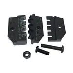
Stückliste der Einzelteile ohne Matrize
Part list of the single parts without dies
Position
Item
Best. Nr.
Part No.
Beschreibung
Description
Menge
Quantity
1
2-539 786-2
Kontaktabstützung
Contact guide
1
2
1-519 151-2
Schraube M4x20
Screw M4x20
1
3
8-539 634-5
Schraube M4x11
Screw M4x11
1
4
0-519 021-8
Mutter M4 DIN 934
Nut M4 DIN 934
1
5
0-744 003-3
Instruction Sheet
411-18233
1
Seite / Page 10 of 11
�Americas
Argentina - Buenos Aires
Phone: +54-1-733-2000
Fax:
+54-1-717-0988
Chile - Santiago
Phone: +56-2-739-1230
Fax:
+56-2-739-1227
Brazil - Sao Paulo
Phone: +55-11-3611-1311
Fax:
+55-11-3611-0397
Colombia - Bogota
Phone: +57-1-231-9398
Fax:
+57-1-240-3769
Canada - Toronto
Phone: +905-475-6222
Fax:
+905-474-5520
Mexico - Mexico City
Phone: +52-5-729-0400
Fax:
+52-5-361-8545
Asia/Pacific
Australia - Sydney
Phone: +61-2-9840-8200
Fax:
+61-2-9899-5649
Fax:
+81-44-844-8733
Korea - Seoul
Phone: +82-2-3274-0535
Fax:
+82-2-3274-0524/0531
India - Bangalore
Phone: +91-80-841-0200
Fax:
+91-80-841-0210
Malaysia - Selangor
Phone: +60-3-7053055
Fax:
+60-3-7053066
Indonesia - Jakarta
Phone: +6221-526-7852
Fax:
+6221-526-7856
New Zealand - Auckland
Phone: +64-9-634-4580
Fax:
+64-9-634-4586
Japan - Kawasaki, Kanagawa
Phone: +81-44-844-8079
Philippines - Makati City
Phone: +632-867-8641
United States - Harrisburg,
PA
Phone: +717-564-0100
Fax:
+717-986-7575
For Latin/South American
Countries not shown
Phone: +54-11-4733-2015
Fax:
+54-11-4733-2083
Venezuela - Caracas
Phone: +58-2-986-7774
Fax:
+58-2-986-9739
Fax:
+632-867-8661
People’s Republic of China
Hong Kong
Phone: +852-2735-1628
Fax:
+852-2735-0243
Shanghai
Phone: +86-21-6485-0602
Fax:
+86-21-6485-0728
Shunde
Phone: +86-765-775-1368
Fax:
+86-765-775-2823
Singapore - Singapore
Phone: +65-482-0311
Fax:
+65-482-1012
Taiwan - Taipei
Phone: +886-2-2664-9977
Fax:
+886-2-2664-9900
Thailand - Bangkok
Phone: +66-2-955-0500
Fax:
+66-2-955-0505
Vietnam - Ho Chi Minh City
Phone: +84-8-8232-546/7
Fax:
+84-8-8221-443
Europe/Middle East/Africa
Austria - Vienna
Phone: +43-190-560-0
Fax:
+43-190-560-1333
Belgium - Kessel-Lo
Phone: +32-16-352-300
Fax:
+32-16-352-352
France
AMP Electronics-ExportSt Ouen L'Aumone
Phone: +33-1-3440-7200
Fax:
+33-1-3440-7220 or
+33-1-3440-7230
Ireland - Dublin
Phone: +353-1-820-3000
Fax:
+353-1-820-9790
Russia - St. Petersburg
Phone: +7-812-325-30-83
Fax:
+7-812-325-32-88
Israel - Yokneam
Phone: +972-4-959-0508
Fax:
+972-4-959-0506
Slovakia - Banska Bystrica
Phone: +421-48-415-20-11/12
Fax:
+421-48-415-20-13
Italy - Collegno (Torino)
Phone: +39-011-4012-111
Fax:
+39-011-4031-116
Slovenia - Ljubljana
Phone: +386-1561-3270
Fax:
+386-1561-3240
Bulgaria - Sofia
Phone: +359-2-971-2152
Fax:
+359-2-971-2153
Great Britain Stanmore Middlesex
Phone: +44-181-954-2356
Fax:
+44-181-954-6234
Czech Republic - Kurim
Phone: +420-5-41-162-111
Fax:
+420-5-41-162-223
Greece - Athens
Phone: +30-1-9370-396/397
Fax:
+30-1-9370-655
Lithuania - Vilnius
Phone: +370-2-2314-02
Fax:
+370-2-2314-03
South Africa - Port Elizabeth
Phone: +27-41-405-4500
Fax:
+27-41-486-1314
Denmark - Viby J
Phone: +45-70-15-52-00
Fax:
+45-86-29-51-33
Germany - Bensheim
Phone: +49-6251-133-0
Fax:
+49-6251-133-1600
Spain - Barcelona
Phone: +34-93-291-0330
Fax:
+34-93-201-7879
Egypt - Cairo
Phone: +20-2-417-76-47
Fax:
+20-2-419-23-34
Germany - Langen
Phone: +49-6103-709-0
Fax:
+49-6103-709-1223
Netherlands ’s-Hertogenbosch
Phone: +31-73-6246-246
Fax:
+31-73-6212-365
Estonia - Tallinn
Phone: +372-65-05-474
Fax:
+372-65-05-470
Germany - Speyer
Phone: +49-6232-30-0
Fax:
+49-6232-30-2243
Finland - Helsinki
Phone: +358-95-12-34-20
Fax:
+358-95-12-34-250
Germany
HTS Division - Neunkirchen
Phone: +49-2247-305-0
Fax:
+49-2247-305-122
France Cergy-Pontoise-Cedex
Phone: +33-1-3420-8888
Fax:
+33-1-3420-8600
Hungary - Budapest
Phone: +36-1-289-1000
Fax:
+36-1-289-1010
Norway - Nesbru
Phone: +47-66-77-88-99
Fax:
+47-66-77-88-55
Poland - Warsaw
Phone: +48-22-5490-888
Fax:
+48-22-5490-880
Sweden - Upplands Väsby
Phone: +46-8-50-72-50-00
Fax:
+46-8-50-72-50-01
Switzerland - Steinach
Phone: +41-71-447-0447
Fax:
+41-71-447-0444
Romania - Bucharest
Phone: +40-1-311-3479 + 3596
Fax:
+40-1-312-0574
Turkey - Istanbul
Phone: +90-212-281-8181...3
+90-212-282-5130/5430
Fax:
+90-212-281-8184
Russia - Moscow
Phone: +7-095-926-55-06...09
Fax:
+7-095-926-55-05
Ukraine - Kiev
Phone: +38-044-238-6908
Fax:
+38-044-568-5740
09-01 GATD
http://www.tycoelectronics.com
Seite / Page 11 of 11
�


 工商网监
湘ICP备2023018690号
工商网监
湘ICP备2023018690号

