Instruction Sheet
408-9830
PRO-CRIMPER* III Hand Tool Assembly
58499-1 with Die Assembly 58483-1
08 AUG 07
Rev E
PROPER USE GUIDELINES
Cumulative Trauma Disorders can result from the prolonged use of manually powered hand tools. Hand tools are intended for occasional use and low volume
applications. A wide selection of powered application equipment for extended-use, production operations is available.
Stationary
Jaw
Back of Tool
(Wire Side)
Pivot Pin
Die Assembly
PRO-CRIMPER III Hand Tool
Moving Jaw
Frame 354940-1 (See Instruction
Sheet 408-9930)
Ratchet Adjustment
Wheel
Stationary Handle
The PRO-CRIMPER III Hand Tool is a Commercial" grade tool and is
designed primarily for field installation, repair, maintenance work, or
prototyping in industrial, commercial, or institutional applications. Product
crimped with this tool will meet the crimp height requirement for hand tools in
Moving Handle
the appropriate Application Specification (114-series), but may not comply
with other feature parameters of the specification. A variety of tools are offered
to satisfy your performance requirements. For additional information, contact
the Tooling Assistance Center at 1-800-722-1111.
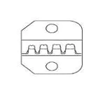
DIE ASSEMBLY
58483-1
PRODUCT
FLEXIBLE COAXIAL
FAMILY
CABLE SIZE (RG/U)
SMB Straight Cable
Plug Connectors
DIE ASSEMBLY
CRIMPING CHAMBER
MARKING
178, 196
.105 (A)
174, 179, 187, 188, 316
.128 (B)
174, 188, 316 (All Double Braid)
.151 (C)
Figure 1
1. INTRODUCTION
NOTE
Dimensions in this instruction sheet are in
millimeters [with inches in brackets]. Figures are
PRO–CRIMPER III Hand Tool Assembly 58499–1
consists of PRO–CRIMPER III Hand Tool Frame
354940–1 and Die Assembly 58483–1. The tool
assembly is used to crimp the ferrule of the
connectors listed in Figure 1. In this use, the die
assembly does not provide for crimping of the center
contact.
For additional information on the hand tool frame,
refer to 408–9930. Refer to the applicable connector
instruction sheet for assembly of the connector.
Read these instructions thoroughly before using the
tool assembly.
Reasons for reissue of this instruction sheet are
provided in Section 8, REVISION SUMMARY.
E
2007 Tyco Electronics Corporation, Harrisburg, PA
All International Rights Reserved
i
not drawn to scale.
TOOLING ASSISTANCE CENTER 1-800-722-1111
This controlled document is subject to change.
PRODUCT INFORMATION 1-800-522-6752
For latest revision and Regional Customer Service,
TE logo and Tyco Electronics are trademarks.
*Trademark. Other products, logos, and company names used are the property of their respective owners.
visit our website at www.tycoelectronics.com
1 of 3
LOC B
�408-9830
PRO-CRIMPER III Hand Tool Assembly 58499-1 with Die Assembly 58483-1
2. DESCRIPTION
4. CRIMPING PROCEDURE
(Figure 1)
The tool frame features a stationary jaw and handle, a
moving jaw, a moving handle, and an adjustable
ratchet that ensures full crimping. The tool frame
holds the die assembly.
The die assembly consists of an indenter (stationary
die) and an anvil (moving die). When closed, the dies
form three crimping chambers. Each die is held in the
hand tool frame by a single screw.
(Ferrule Only)
Make sure that the center contact is properly crimped
and assembled onto the connector as described in
applicable connector instruction sheet. Then proceed
as follows:
1. Slide the ferrule over the cable braid until it is
positioned against the shoulder of the plug body.
2. Close the tool handles until the ratchet releases,
then allow the handles to open FULLY.
3. Place the ferrule in the appropriate crimping
chamber on the anvil die so that the shoulder of
the plug body is close to the edge of the die. Refer
to Figure 3.
3. INSTALLATION AND REMOVAL OF
DIE ASSEMBLY (Figure 2)
1. Close the tool handles until the ratchet releases,
then allow the handles to open fully.
2. Insert the dies into the tool jaws as shown in
Figure 2, and align the retaining holes in each die
with the associated hole in the tool.
NOTE
Refer to Figure 1 for the appropriate crimping
chamber.
i
Tool Frame
Jaws
Indenter
Shoulder of Plug
Body Close to
Edge of Die
Crimping
Chamber
(Ref)
Figure 3
4. While holding the assembly, close the tool
handles until the dies hold the ferrule in place.
Die Retaining
Anvil
Screws
6. Remove the ferrule from the dies.
Figure 2
3. Thread, but do not tighten, the die retaining
screws into the holes.
4. Carefully close the tool handles, making sure
that the dies align properly.
5. Tighten the die retaining screws with the
appropriate hex wrench.
6. To disassemble, close the tool handles until the
ratchet releases, remove the two die retaining
screws, and slide the dies out of the tool jaws.
2 of 3
5. Carefully close the tool handles until the ratchet
releases, then allow the handles to open FULLY.
7. Inspect the crimped ferrule according to
applicable connector instruction sheet. If
necessary, adjust the ratchet as described in
Section 5.
5. RATCHET ADJUSTMENT (Figure 4)
The tool ratchet mechanism features an adjustment
wheel with numbered settings. The adjustment wheel
controls the amount of handle pressure exerted on
the jaws during crimping. If the crimp is not
acceptable, adjust the ratchet as follows:
1. Remove the lockscrew from the ratchet
adjustment wheel.
Tyco Electronics Corporation
Rev
E
�408-9830
PRO-CRIMPER III Hand Tool Assembly 58499-1 with Die Assembly 58483-1
6.3. Measuring Die Opening
Screwdriver
Figure 5 provides dimensions for the die openings.
C
A
Ratchet
Adjustment
Wheel
B
Lockscrew
Figure 4
2. With a screwdriver, adjust the ratchet wheel
from the front of the tool.
3. Observe the ratchet adjustment wheel. If a
tighter crimp is required, rotate the adjustment
wheel counterclockwise to a higher–numbered
setting. If a looser crimp is required, rotate the
adjustment wheel clockwise to a lower–numbered
setting.
4. Re–assemble the lockscrew.
5. Make a sample crimp. If the crimp is acceptable,
the adjustment setting is correct. If the crimp is
unacceptable, continue to adjust the ratchet, and
again measure a sample crimp.
DIE OPENING DIMENSION +0.10 [+.004]
A
B
C
2.667 [.105]
3.251 [.128]
3.835 [.151]
Figure 5
7. REPLACEMENT
Customer–replaceable parts are shown in Figure 1.
Available separately, Repair Kit 679221–1 includes a
replacement nut and a variety of pins, rings, screws,
and springs. If the dies are damaged or worn
excessively, they must be replaced. Order the repair
kit and replaceable parts through your representative,
or call 1–800–526–5142, or send a facsimile of your
purchase order to 717–986–7605, or write to:
CUSTOMER SERVICE (038–035)
TYCO ELECTRONICS CORPORATION
PO BOX 3608
HARRISBURG PA 17105–3608
6. MAINTENANCE AND INSPECTION
6.1. Maintenance
Ensure that the tool frame and dies are clean by
wiping them with a clean, soft cloth. Remove any
debris with a clean, soft brush. Do not use objects
that could damage any components. When not in use,
keep tool handles closed to prevent objects from
becoming lodged in the dies, and store in a clean, dry
area.
8. REVISION SUMMARY
Revisions to this instruction sheet include:
S Updated document to corporate requirements
6.2. Visual Inspection
Inspection of the dies should be made on a regular
basis to ensure that they have not become worn or
damaged. Inspect the crimping sections for flattened,
chipped, worn, or broken areas. If damage or
abnormal wear is evident, the dies must be replaced.
Refer to Section 7, REPLACEMENT.
Rev
E
Tyco Electronics Corporation
3 of 3
�