Instruction Sheet
408-1826
Post-Insulated STRATO-THERM*
Terminal and Splice Die Assemblies
Rev E
Reasons for reissue are given in Section 7,
REVISION SUMMARY.
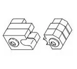
Crimping
Upper Die
22 JAN 09
Chamber
(Stationary)
2. DESCRIPTION
(Figure 1)
Each die assembly consists of an upper die
(stationary) and a lower die (moving), each marked
with the wire size. When mated, the dies form the
crimping chamber. Each die is held in the crimping
head by a single screw.
3. DIE ASSEMBLY INSTALLATION AND REMOVAL
3.1. Installation
Before installing the die assembly, install the crimping
head onto the power unit as described in Instruction
Sheets 408–2458 or 408–8959, and Customer
Manuals 409–1950 or 409–10081.
Lower Die
(Moving)
DANGER
To avoid personal injury, exercise extreme
caution when using the power unit. Avoid
depressing the foot switch or trigger control when
installing or removing die assembly.
1. Loosen the setscrew in the top of the crimping
head and insert shank on upper die, making sure
that the shank is facing the setscrew. Refer to
Figure 2. Tighten setscrew just enough to hold die
in place.
DYNA-CRIMP
Crimping Head
69099 (Ref)
2. Activate the power unit by depressing the foot
switch or trigger control with short, quick strokes.
Advance the ram until the setscrew in the ram is
visible.
Figure 1
1. INTRODUCTION
Post–Insulated STRATO–THERM Terminal
and Splice Die Assemblies 69211–[ ], 69212–[ ],
69213–[ ], 69214–[ ], 69215–[ ], and 69254–[ ] are
used in conjunction with DYNA–CRIMP* Crimping
Head 69099 or 1752868–1 and Hydraulic Power Unit
69120–[ ] or 1804700–[ ] to crimp the insulating
sleeve of Post–Insulated STRATO–THERM Terminals
and Splices. The die assembly is selected according
to the wire size being used.
Refer to Instruction Sheets 408–2458 or 408–8959
(supplied with crimping head) and Customer Manuals
409–1950 or 409–10081 (supplied with power unit) for
tooling information. Product part number information
is available in Catalog 82011.
NOTE
Align Lower Die
Setscrew
with Upper Die,
Slide Lower Die
In and Center
Shank Over
Ram Well
Flat on
Shank
Ram Well
Ram
Setscrew
All dimensions on this document are in
millimeters [with inches in brackets]. Figures and
i
illustrations are for reference only and are not
drawn to scale.
E
2009 Tyco Electronics Corporation, Harrisburg, PA
All International Rights Reserved
Figure 2
TOOLING ASSISTANCE CENTER 1-800-722-1111
This controlled document is subject to change.
PRODUCT INFORMATION 1-800-522-6752
For latest revision and Regional Customer Service,
TE logo and Tyco Electronics are trademarks.
*Trademark. Other products, logos, and company names used are the property of their respective owners.
visit our website at www.tycoelectronics.com
1 of 4
LOC B
�408-1826
Post-Insulated STRATO-THERM Die Assemblies
4. CRIMPING PROCEDURE
3. Engage the holding device on the power unit so
that the ram stays in position.
1. Assemble the insulating sleeve over the crimped
wire barrel of the terminal or splice as shown in
Figure 3. Make sure the bushing butts against, but
does not slide over, the crimped cartridge.
4. Loosen the ram setscrew.
5. Align the lower die with the upper die as shown
in Figure 2. Insert the shank on the lower die
partially into the ram well, making sure the shank is
facing the setscrew. Do NOT allow the dies to
become disengaged.
2. Check that the insulating sleeve extends
approximately 0.80 mm [.031 in.] from the ring and
that the bushing extends approximately 0.80 mm
[.031 in.] from the insulating sleeve. Refer to
Figure 3.
6. Activate the power unit and advance the ram
just enough to move the lower die to its topmost
position before completing a cycle.
NOTE
the bushing must butt against the wire barrel. For
7. Engage the holding device. Tighten both
setscrews.
NOTE
i
other and are firmly seated in the crimping head.
insulating sleeve to extend 0.80 mm [.031 in.]
3. Center the ring on the insulating sleeve in
the crimping chamber of the stationary die.
See Figure 4.
i
8. Activate power unit and allow the ram to return
to the ‘‘DOWN” position.
an insulating sleeve without a bushing, allow
beyond the wire barrel.
Ensure that the dies are properly aligned to each
DANGER
If terminal or splice does not contain a cartridge,
DANGER
To avoid personal injury or damage to the tool,
always keep fingers clear of dies.
To avoid personal injury or damage to the tool,
check setscrews occasionally to ensure that they
are fully tightened when tool is in use.
4. Activate power unit to complete the crimp.
3.2. Removal
5. To crimp the other half of a splice, reposition the
uncrimped side in the crimping chamber.
Loosen setscrew in top of crimping head and remove
upper die. Raise the ram until the ram setscrew is
visible. Loosen ram setscrew and remove lower die.
Ring
Assembling
6. Remove crimped terminal or splice from die and
inspect the crimp.
Bushing
Crimped Wire
a Terminal
Insulating
Barrel of Terminal
Sleeve
Sleeve Extended
Approximately
0.80 mm [.031 in.]
from Ring
Bushing Butts Against
Crimped Cartridge
Bushing Extended
Approximately 0.80 mm
[.031 in.] from Insulating
Sleeve
Insulating
Sleeve
Assembling
Crimped Wire Barrels of Splice
Ring
Bushing
a Splice
Insulating Sleeve
Bushing Extended
Centered Over Splice
Approximately 0.80 mm
[.031 in.] from Insulating
Sleeve Extended Approximately
Sleeve
Figure 3
2 of 4
Tyco Electronics Corporation
0.80 mm [.031 in.] from Ring
Rev
E
�408-1826
Post-Insulated STRATO-THERM Die Assemblies
5.1. Cleaning
Crimping a
Terminal
1. Remove accumulated dirt, grease, and foreign
matter from die closure surfaces of the dies. Wipe
dies frequently with a soft, lint–free cloth. Do NOT
use hard or abrasive objects that could damage
the dies.
Stationary
Die
2. When die assembly is not in use, mate and
store the dies in a clean, dry area.
Cable
5.2. Periodic Inspection
A. Visual Inspection
Inspect die closure surfaces of the dies for worn,
cracked, or broken areas. If damage is evident, return
the die assembly to Tyco Electronics for evaluation
and repair. See Section 6, REPLACEMENT.
Ring on Insulating Sleeve
Centered in Crimping
Chamber of Upper Die
Crimping a
Splice
B. Gaging the Crimping Chamber
This inspection requires the use of a plug gage
conforming to the dimensions shown in Figure 5. Tyco
Electronics does not manufacture or market these
gages. To gage the crimping chamber, proceed as
follows:
Stationary
Die
Cable
1. Remove traces of oil or dirt from the crimping
chamber and plug gage.
2. Mate and adjust dies to meet the gage
dimension shown in Figure 6.
Ring on Insulating Sleeve
Centered in Crimping
Chamber of Upper Die
3. With dies positioned at the gage dimension,
align the GO element with the crimping chamber
(opposite side of part number markings). Push the
element (without forcing it) straight into the
chamber. The GO element must pass completely
through the first three laminations.
Figure 4
5. MAINTENANCE AND INSPECTION PROCEDURE
Tyco Electronics recommends that a maintenance
and inspection program be performed periodically to
ensure dependable and uniform terminations. Though
recommendations call for at least one inspection a
month, frequency of inspection depends on:
4. Align and try to insert the NO–GO element with
the same crimping chamber. The NO–GO element
may start entry but must not pass completely
through the crimping chamber.
1. The care, amount of use, and handling of the
die assembly.
If the crimping chamber conforms to the gage
inspection, the die assembly is considered
dimensionally correct. If not, the die assembly must
be replaced before returning it to service. See Section
6, REPLACEMENT.
2. The presence of abnormal amounts of dust and
dirt.
6. REPLACEMENT
3. The degree of operator skill.
4. Your own established standards.
The die assembly is inspected before being shipped;
however, Tyco Electronics recommends that the die
assembly be inspected in accordance with Paragraph
5.2.B, Gaging the Crimping Chamber, immediately
upon arrival at your facility to ensure that the dies
have not been damaged during shipment.
Rev E
If the die assembly is damaged or worn, it must be
replaced. Order replacement die assemblies through
your Tyco Electronics Representative, or call
1–800–526–5142, or send a facsimile of your
purchase order to 1–717–986–7605, or write to:
CUSTOMER SERVICE (38–35)
TYCO ELECTRONICS CORPORATION
P.O. BOX 3608
HARRISBURG, PA 17105–3608
Tyco Electronics Corporation
3 of 4
�408-1826
Post-Insulated STRATO-THERM Die Assemblies
SUGGESTED PLUG GAGE
DESIGN
GO Dim.
DIES POSITIONED AT GAGE DIMENSION
NO-GO
Dim.
Die Closure
50.8 [2.00]
ÉÉ
ÉÉ
ÉÉ
ÉÉ
(Min Typ)
Crimping Chamber
GO Element
ÉÉ
ÉÉ
ÉÉ
ÉÉ
42.26
[1.664]
Gage
Dim.
NO-GO Element
GO element must pass
NO-GO element may enter
completely through the
partially, but must not pass
first three laminates.
completely through the die
Figure 6
closure.
DIE ASSEMBLY
PART NUMBER
69211-[ ]
69212-[ ]
69213-[ ]
69214-[ ]
69215-[ ]
69254-[ ]
GAGE ELEMENT DIMENSIONS
GO
NO-GO
7.950-7.958
8.151-8.153
[.3130-.3133]
[.3209-.3210]
9.677-9.685
9.878-9.881
[.3810-.3813]
[.3889-.3890]
11.252-11.260
11.453-11.455
[.4430-.4433]
[.4509-.4510]
12.979-12.987
13.180-13.183
[.5110-.5113]
[.5189-.5190]
15.316-15.324
15.517-15.519
[.6030-.6033]
[.6109-.6110]
21.082-21.090
21.283-21.285
[.8300-.8303]
[.8379-.8380]
7. REVISION SUMMARY
Revisions to this document include:
S Updated document to corporate requirements
S Changed dimensions in Figure 6
Figure 5
4 of 4
Tyco Electronics Corporation
Rev
E
�