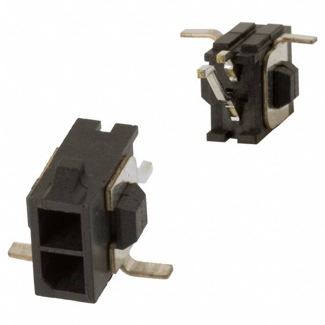
Product
Specification
108-1836
09 FEB 16 Rev E
3 mm Micro MATE-N-LOK* Connector
1.
SCOPE
1.1.
Content
This specification covers performance, tests and quality requirements for the 3 mm Micro MATE-NLOK* connector family. This connector family has wire-to-board and wire-to-wire configurations. The
connectors are available in 2 to 24 positions in a double row configuration, and 2 to 12 positions in a
single row configuration, with both configurations using 20 to 30 AWG wire.
1.2.
Qualification
When tests are performed on the subject product line, procedures specified in Figure 1 shall be used. All
inspections shall be performed using the applicable inspection plan and product drawing.
1.3.
Qualification Test Results
Successful qualification testing on the subject product line was completed on 16Jan02. The Qualification
Test Report number for this testing is 501-526. This documentation is on file at and available from
Engineering Practices and Standards (EPS).
2.
APPLICABLE DOCUMENTS
The following documents form a part of this specification to the extent specified herein. Unless
otherwise specified, the latest edition of the document applies. In the event of conflict between the
requirements of this specification and the product drawing, the product drawing shall take precedence.
In the event of conflict between the requirements of this specification and the referenced documents, this
specification shall take precedence.
2.1.
TE Connectivity (TE) Documents
•
•
•
2.2.
109-197: Test Specification (TE Test Specifications vs EIA and IEC Test Methods)
501-526: Qualification Test Report (3 mm Micro MATE-N-LOK* Connector)
502-139105: Engineeering test report (Resistance to soldering heat)
Commercial Standard
EIA-364: Electrical Connector/Socket Test Procedures Including Environmental Classifications
3.
REQUIREMENTS
3.1.
Design and Construction
Product shall be of the design, construction and physical dimensions specified on the applicable product
drawing.
3.2.
Materials
Materials used in the construction of this product shall be as specified on the applicable product
drawing.
3.3.
Ratings
•
•
•
3.4.
Voltage: 250 volts AC or DC
Current: See Figure 1 for applicable current carrying capability
Temperature: -40 to 105°C
Test Requirements and Procedures Summary
Unless otherwise specified, all tests shall be performed at ambient environmental
© 2016 TE Connectivity family of companies
All Rights Reserved
| Indicates Change
This controlled document is subject to change.
For latest revision and Regional Customer Service, visit our website at www.te.com
PRODUCT INFORMATION 1-800-522-6752
*Trademark. TE Connectivity, TE connectivity (logo), and TE (logo) are trademarks. Other logos, product, and/or company names may be trademarks of their respective owners.
1 of 6
�108-1836
Test Description
Requirement
Initial examination of product.
Meets requirements of product
drawing.
Final examination of product.
Meets visual requirements.
Procedure
EIA-364.
Visual and dimensional (C of C)
inspection per product drawing.
EIA-364.
Visual inspection.
ELECTRICAL
Termination resistance.
20 milliohms maximum.
EIA-364-23.
Subject specimens to 100
milliamperes maximum and 20
millivolts maximum open circuit
voltage.
See Figure 3.
Insulation resistance.
1000 megohms initial.
100 megohms final.
EIA-364-21.
Test between adjacent contacts of
mated specimens.
Dielectric withstanding voltage.
1 minute hold with no breakdown,
flashover, or 0.5 milliampere
maximum leakage.
EIA-364-20, Condition I.
1500 volts AC at sea level.
Test between adjacent contacts of
mated specimens.
Temperature rise vs current.
30°C maximum temperatur e rise at EIA-364-70, Method 1.
specified current (100% energized). Stabilize at a single current level
until 3 readings at 5 minute intervals
Wire Size Connector Amperes
are within 1°C.
(AWG)
Position
20
2 to 6
5
20
8 to 24
4.25
28
2 to 20
2
28
22 to 24
1.8
MECHANICAL
Solderability, dip test.
Solderable area shall have a
minimum of 95% solder coverage.
EIA-364-52,
Category 3 For thru-hole.
EIA-638 for surface mount.
Subject contacts to solderability.
Heat Resistance to Reflow
Soldering.
See note
TEC-109-201
Subject contacts to reflow soldering.
Crimp tensile.
Wire Size
(AWG)
20
22
24
26
28
30
Crimp Tensile
(kg [lb] minimum)
7.95 [17.5]
5.00 [11]
3.60 [7.9]
2.05 [4.5]
1.40 [3.1]
0.77 [1.7]
EIA-364-8.
Determine crimp tensile at a
maximum rate of 25 ± 6 mm [0.98 ±
0.24 in] per minute.
Figure 1 Cont.
Rev E
2 of 6
�108-1836
Test Description
Vibration, random.
Requirement
Procedure
Mechanical shock.
No discontinuities of 1 microsecond EIA-364-28, Test Condition VII,
or longer duration.
Condition D.
See Note.
Subject mated specimens to 3.10
G's rms between 20-500 Hz. 15
minutes in each of 3 mutually
perpendicular planes.
See Figure 4.
No discontinuities of 1 microsecond EIA-364-27, Method A.
or longer duration.
Subject mated specimens to 50 G's
See Note.
half-sine shock pulses of 11
milliseconds duration. 3 shocks in
each direction applied along 3
mutually perpendicular planes, 18
total shocks.
See Figure 4.
Durability.
See Note.
Header contact retention.
Contact shall not dislodge.
See Note.
Crimp contact retention.
Contact shall not dislodge.
See Note.
EIA-364-29.
Apply an axial load of 1.81 kg [4 lb]
to contacts at a rate of 0.45 kg [1 lb]
per second and hold for 6 seconds.
Crimp contact insertion force.
0.7 kg [1.5 lb] maximum.
See Note.
TE Spec 109-41.
Measure force necessary to insert
crimped contacts into housing.
Mating force (contacts only).
0.7 kg [1.5 lb] maximum per
contact.
EIA-364-13.
Measure axial force necessary to
mate specimens without locking
latches at a maximum rate of 5.08
mm [.2 in] per minute.
Unmating force (contacts only).
0.07 kg [0.15 lb] minimum per
contact.
EIA-364-13.
Measure axial force necessary to
unmate specimens without locking
latches at a maximum rate of 12.7
mm [.5 in] per minute.
Housing lock strength.
2.7 kg [6 lb] minimum.
EIA-364-98.
Determine housing lock strength at
a maximum rate of 12.7 mm [0.5 in]
per minute.
EIA-364-9.
Mate and unmate specimens for 30
cycles for tin plated specimens, 75
cycles for 15 µin gold plated
specimens, and 150 cycles for 30
µin gold plated specimens at a
maximum rate of 500 cycles per
hour.
EIA-364-29.
Apply an axial load of 1.4 kg [3.1 lb]
to contacts at a rate of 0.45 kg [1 lb]
per second and hold for 6 seconds.
Figure 1 Cont.
Rev E
3 of 6
�108-1836
Test Description
Requirement
Procedure
ENVIRONMENTAL
Thermal shock.
See Note.
EIA-364-32, Test Condition VIII.
Subject specimens to 5 cycles
between -40 and 105°C.
Humidity/temperature cycling.
See Note.
EIA-364-31, Method III.
Subject specimens to 10 cycles (10
days) between 25 and 65°C at 80 to
100% RH.
Temperature life.
See Note.
EIA-364-17, Method A, Test
Condition 4, Test Time Condition C.
Subject mated specimens to 105°C
for 500 hours.
Mixed flowing gas.
See Note.
EIA-364-65, Class IIA.
Subject mated specimens to
environmental Class IIA for 20 days.
NOTE
Shall meet visual requirements, show no physical damage, and meet requirements of additional
tests as specified in the Product Qualification and Requalification Test Sequence shown in
Figure 2.
Figure 1 (end)
Rev E
4 of 6
�108-1836
1.1.
Product Qualification and Requalification Test Sequence
Test Group (a)
1
Test or Examination
2
3
4
5
6
1
1
Test Sequence (b)
Initial examination of product
1
1
Termination resistance
3,7
2,6
1
Insulation resistance
3,7
Dielectric withstanding
lt
Temperature
rise vs current
4,8
1
3,7
Solderability, dip test
2
Heat Resistance to Reflow
Soldering
2
Crimp tensile
2
Vibration, random
5
Mechanical shock
6
Durability
4
Header contact retention
10(c)
Crimp contact retention
11
Crimp contact insertion force
2
Mating force (contacts only)
2
Unmating force (contacts
l )
Housing
lock strength
8
9
Thermal shock
5
Humidity/temperature cycling
4(d)
Temperature life
5
Mixed flowing gas
4(d)
Final examination of product
9
8
6
12
3
3
3
NOTE
a. Specimens shall be prepared in accordance with applicable Instruction Sheets and shall be
selected at random from current production. All test groups shall each consist of a minimum
of 5 specimens.
b. Numbers indicate sequence in which tests are performed.
c. Test omitted when testing wire-to-wire connectors.
d. The fourth test in this sequence will be either humidity/temperature cycling for tin plated
specimens or mixed flowing gas for gold plated specimens. Precondition specimens with 10
cycles of durability.
Figure 2
Rev E
5 of 6
�108-1836
NOTE
Resistance due to X length of wire is to be removed from all readings.
Figure 3
Termination Resistance Measurement
Points
Figure 4
Vibration & Mechanical Shock Mounting
Fixture
Rev E
6 of 6
�
很抱歉,暂时无法提供与“794629-2”相匹配的价格&库存,您可以联系我们找货
免费人工找货- 国内价格 香港价格
- 3000+8.862693000+1.14659