Hex Crimp Die Assemblies 9-1478243-0,
9-1478245-0, and 9-1478247-0 (used with
SDE-SA Hand Tool Assembly 9-1478240-0)
Instruction Sheet
408-8696
28 SEP 10 Rev B
PROPER USE GUIDELINES
Cumulative Trauma Disorders can result from the prolonged use of manually powered hand tools. Hand tools are intended for occasional use
and low volume applications. A wide selection of powered application equipment for extended-use, production operations is available.
Stationary Jaw
Hand Tool Frame
9-1478240-0
Nest Die
Anvil Die
Moving Jaw
Typical Die Assembly
Figure 1
1. INTRODUCTION
This instruction sheet covers the use and maintenance
of SDE-SA Crimping Dies 9-1478243-0, 9-1478245-0,
and 9-1478247-0 (previously designed for
GREENPAR connectors) in their various
configurations - denoted by the dash numbers . See
the table in Figure 1.
Also shown is the base hand tool frame, the connector
types and the type of coaxial cable used.
Reason for revision may be found in Section 8,
REVISION SUMMARY.
NOTE
i
All dimensions are in millimeters [with inches in
brackets].
2. DESCRIPTION
Each die assembly consists of a nest die and an anvil
die. When closed, the dies form two crimping
chambers which crimp the center contact and ferrule
of the connector onto the coaxial cable. Each die is
held in the tool by a single screw.
3. DIE INSTALLATION
1. Close the tool handles until the ratchet
releases and then allow them to open fully.
2. See Figure 1 for normal orientation of the dies.
Insert the dies inside the tool jaws and align the
retaining screw holes.
3. Thread the retaining screws into the holes and
carefully close the tool handles. Tighten the
screws with the appropriate hex wrench.
4. CRIMPING PROCEDURE
Refer to Figure 2.
4.1. Center Contact
1. Prepare the connector and the cable according
to the instructions packaged with the connector.
GREENPAR was a trademark of GREENPAR Engineering Limited. Essex, England.
©2010 Tyco Electronics Corporation, Berwyn, PA
TOOLING ASSISTANCE CENTER 1-800-722-1111
All Rights Reserved
PRODUCT INFORMATION 1-800-522-6752
TE logo and Tyco Electronics are trademarks.
*Trademark. Other products, logos, and company names might be trademarks of their respective owners.
This controlled document is subject to change.
For latest revision and Regional Customer Service,
visit our website at www.tycoelectronics.com
1 of 3
LOC B
�408-8696
4.2. Ferrule
Insert Center Contact
into Partially Closed
Crimping Dies
1. Insert the crimped center contact into the
connector body until the cable dielectric butts
against the dielectric inside of the connector
body. The flared braid will then fit around the
support sleeve of the connector body.
Center Contact
Slipped Over
Center Conductor
2. Slide the ferrule forward over the braid until
the ferrule butts against the shoulder on the
connector body.
3. Place the ferrule on the anvil of the die
assembly so that the shoulder on the connector
body is butted against the die. See Figure 4.
4. Holding the assembly in place, close the tool
handles until the ratchet releases.
Crimping Ferrule
Ferrule (Ref)
Crimping Die
(Ref)
Figure 2
Shoulder on
Connector Body
Butts Against Die
2. Slide the center contact onto the center
conductor of the cable; then insert the contact
assembly into the center contact crimp section of
the die.
NOTE
i
Make sure that the flange on the end of the center
contact butts against the crimping die. See
Figure 3.
3. Crimp the center contact by holding the cable
in place; then close the tool handles until the
ratchet releases.
Ferrule on Anvil
of Crimping Die
Typical RF
Connector (Ref)
Flange on End of Center
Contact Butts Against Die
Flange on End
of Contact
Crimping
Die
Figure 4
5. INSPECTION
5.1. Visual Inspection
Inspection of the crimping dies should be made on a
regular basis to ensure that they have not become
worn or damaged. Inspect the crimp sections for
flattened, chipped, worn, or broken areas. If damage
or abnormal wear is evident, the dies must be
replaced. Refer to Section 7, PARTS
REPLACEMENT.
5.2. Measuring Die Opening
The die assembly will perform correctly as long as:
Figure 3
1. The product specified is correct for the
application;
2. The specific die assembly is used;
Rev B
2 of 3
�408-8696
3. The die assembly has been measured to
ensure that the openings are correct; and
4. The tool has been adjusted correctly.
Figure 5 provides information on die opening sizes.
10.16
[.400]
If the crimp cannot be made to conform to the
dimensions provided in the appropriate product
application specification, the tool and/or dies are
defective and must be replaced.
NOTE
i
Other crimping dies for use with GREENPAR
connectors may be used in this tool; however, the
ratchet adjustment wheel may require adjustment
to achieve acceptable crimp height.
6. DAMAGED CONTACTS AND FERRULES
CAUTION Damaged contacts or ferrules may not be used. If
a center contact or ferrule is damaged during the
crimping operation, it must be replaced with a new
!
one.
7. PARTS REPLACEMENT
If the dies are damaged or worn excessively, they
must be replaced. Order replacement dies through
your Tyco Electronics Representative, or call 1-800526-5142, or send a facsimile of your purchase order
to 1-717-986-7605, or write to:
DIE ASSEMBLY
PART NUMBER
CHAMBER CRIMP DIMENSION
“A”±0.10 [.004]
9-1478243-0
9-1478245-0
“B”±0.10 [.004]
8.20 [.323]
1.75 [.069]
9-1478247-0
4.75 [.187]
CUSTOMER SERVICE (038-035)
TYCO ELECTRONICS CORPORATION
PO BOX 3608
HARRISBURG PA 17105-3608
8. REVISION SUMMARY
Since the previous release, the TE logo was applied.
7.50 [.295]
Figure 5
5.3. Ratchet Adjustment
The tool frame assembly ratchet mechanism features
an adjustment wheel with nine settings. The
adjustment wheel controls the amount of handle
pressure exerted on the tool jaws and crimping dies
during crimping. If the crimp is not acceptable, adjust
the ratchet as follows:
1. Remove the screw at the ratchet adjustment
wheel so that the wheel can be rotated.
2. If the crimp is too loose, turn the wheel to a
higher notch. If the crimp is too tight, move the
wheel to a lower notch.
3. Replace and tighten the screw at the ratchet
adjustment wheel.
Rev B
3 of 3
�
很抱歉,暂时无法提供与“9-1478247-0”相匹配的价格&库存,您可以联系我们找货
免费人工找货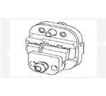


 工商网监
湘ICP备2023018690号
工商网监
湘ICP备2023018690号