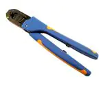
Instruction Sheet
408–7270
Hand Crimping Tool 90188–2
16 SEP 99
Rev C
PROPER USE GUIDELINES
Cumulative Trauma Disorders can result from the prolonged use of manually powered hand tools. AMP hand tools are intended for occasional use and low
volume applications. AMP offers a wide selection of powered application equipment for extended–use, production operations.
The CERTI–CRIMP ratchet ensures full crimping of
the terminal. Once engaged, the ratchet will not
release until the handles have been FULLY closed.
F
AMP
Crimpers
Front of
Tool
90188–2
CAUTION
Anvils
The crimping dies bottom before the
CERTI–CRIMP ratchet releases. This is a design
feature that assures maximum electrical and
tensile performance of the crimp. Do NOT
re–adjust the ratchet.
3. CRIMPING PROCEDURE
Select an applicable terminal and a wire of
appropriate size and insulation diameter. Strip the
wire to the length indicated in Figure 2. Do NOT cut
or nick the wire strands.
1. Hold the tool so the BACK of it is facing you.
2. Make certain that the ratchet is released by
squeezing the tool handles and allowing them to
open FULLY.
3. Looking straight into the crimping dies from the
BACK of the tool, insert a terminal (insulation
barrel first) into the FRONT of the appropriate
crimping section.
CERTI–CRIMP*
Ratchet
4. Position the terminal in the crimpers so that the
locator/insulation stop enters the terminal locator
slot.
Figure 1
1. INTRODUCTION
This instruction sheet covers application and
maintenance for AMP* Hand Crimping Tool 90188–2,
which is designed to crimp quick–disconnect–type
terminals having open wire and insulation barrels. A
typical terminal is shown in Figure 2. Read these
instructions carefully before applying any terminals.
NOTE
All dimensions on this sheet are in metric units
[with U.S. customary units in brackets].
Reasons for reissue are provided in Section 6,
REVISION SUMMARY.
5. Hold the terminal in this position and squeeze
the tool handles until the insulation anvil starts
entry into the insulation crimper. Do NOT deform
the insulation barrel or wire barrel.
Insulation
Barrel
Typical
Terminal
Wire
Barrel
2. DESCRIPTION (Figures 1 and 2)
Locator
Slot
This tool features two fixed dies (crimpers), two
movable dies (anvils), a locator/insulation stop, and a
CERTI–CRIMP ratchet.
The locator/insulation stop positions the terminal
between the crimping dies and aids in locating the
wire in the terminal. In use, it rests in the terminal’s
locator slot.
E1999 AMP Incorporated, Harrisburg, PA.
All International Rights Reserved.
*Trademark
Wire Strip
Length
This controlled document is subject to change.
For latest revision call the AMP FAX* number.
Terminal Wire Barrel
Length +.76 [+.030 in.].
Figure 2
TOOLING ASSISTANCE CENTER 1–800–722–1111
AMP FAX/PRODUCT INFO 1–800–522–6752
1 of 4
LOC B
408–7270
Hand Crimping Tool 90188–2
Back of Tool
(Wire Side)
Crimp Section
Letter Marking
B
Typical
Terminal
A
Locator/
Insulation
Stop
Wire
Barrel
Locator in
Wire Slot
Terminal
Locator
Slot
Stripped
Wire
Insulation
Barrel
Figure 3
6. Insert a properly stripped wire through the
locator wire slot and into the wire barrel of the
terminal until the insulation butts against the
locator/insulation stop.
7. Hold the wire in place and squeeze the tool
handles until the ratchet releases.
8. Allow the tool handles to open FULLY and
remove the crimped terminal.
4. MAINTENANCE/INSPECTION
AMP recommends that a maintenance and inspection
program be performed periodically to ensure
dependable and uniform terminations. Frequency of
inspection depends on:
1. The care, amount of use, and handling of the
hand tool.
2. The presence of abnormal amounts of dust and
dirt.
3. The degree of operator skill.
4. Your own established standards.
4.1. Daily Maintenance
1. Remove dust, moisture, and other contaminants
with a clean brush, or a soft, lint–free cloth. Do
NOT use objects that could damage the tool.
2 of 4
2. Make certain that the retaining pins are in place
and that they are secured with retaining rings.
3. When the tool is not in use, keep handles closed
to prevent objects from becoming lodged in the
crimping dies. Store the tool in a clean, dry area.
4.2. Lubrication
Lubricate all pins, pivot points, and bearing surfaces
with SAE 20 motor oil as follows:
Tools used in daily production—lubricate daily
Tools used daily (occasional)—lubricate weekly
Tools used weekly—lubricate monthly
Wipe excess oil from tool, particularly from crimping
area. Oil transferred from the crimping chambers onto
certain terminations may affect the electrical
characteristics of an application.
4.3. Periodic Inspection
1. Hand tool should be immersed (handles partially
closed) in a reliable commercial degreasing
compound to remove accumulated dirt, grease,
and foreign matter.
2. Close tool handles until the CERTI–CRIMP
ratchet releases and then allow them to open fully.
If the handles do not open quickly and fully, the
spring is defective and must be replaced. Refer to
Section 5, REPLACEMENT AND REPAIR.
Rev C
408–7270
Hand Crimping Tool 90188–2
3. Inspect tool head for worn, cracked, or broken
dies. If damage is evident, return tool to AMP for
evaluation and repair. See Section 5,
REPLACEMENT AND REPAIR.
4.4. Crimp Height Inspection
This inspection requires the use of a micrometer with
a modified anvil , as shown in Figure 4. AMP
recommends the use of a modified micrometer (Crimp
Height Comparator RS–1019–5LP) which can be
purchased from:
Shearer Industrial Supply Co.
20 North Penn Street
York, PA 17401–1014
or
VALCO
1410 Stonewood Drive
Bethlehem, PA 18017–3527
1. Refer to the table in Figure 4 and select wire
(maximum size) for each crimp section listed in the
chart.
2. Refer to Section 3, CRIMPING PROCEDURE,
and crimp the contact accordingly.
3. Using a crimp height comparator, measure the
wire barrel crimp height as shown in Figure 4. If the
crimp height conforms to that shown in the chart,
the tool is considered dimensionally correct. If not,
return the tool to AMP for evaluation and repair
(see Section 5, REPLACEMENT AND REPAIR).
For additional information concerning the use of the
crimp height comparator, refer to AMP instruction
sheet 408–7424.
Position Point
on Center of
Wire Barrel
Opposite Seam
4.5. CERTI–CRIMP Ratchet Inspection
The CERTI–CRIMP ratchet feature on the hand tool
should be checked to ensure it does not release
prematurely, allowing the crimping dies to open before
they have fully bottomed. Obtain a 0.025–mm
[.001–in.] shim that is suitable for checking the
clearance between the bottoming surfaces of the
crimping dies. Proceed as follows:
1. Select the maximum size wire and strip it
according to the dimensions listed in Figure 2.
2. Select the appropriate crimp section. See
Figure 2.
3. Position contact and wire between the crimping
dies, as described in Section 3, CRIMPING
PROCEDURE.
4. Hold wire in place and squeeze tool handles
together until the CERTI–CRIMP ratchet releases.
Hold tool handles in this position, maintaining just
enough tension on the handles to keep the dies
closed.
5. Check the clearance between the bottoming
surfaces of the crimping dies. If the clearance is
0.025 mm [.001 in.] or less, the ratchet is
satisfactory. If clearance exceeds 0.025 mm
[.001 in.], the ratchet is out of adjustment and must
be repaired. See Section 5, REPLACEMENT AND
REPAIR.
5. REPLACEMENT AND REPAIR
Replacement parts are listed in Figure 5. Parts other
than those listed in Figure 5 should be replaced by
AMP to ensure quality and reliability of the tool.
Modified
Anvil
TERMINAL
NUMBER
MBER
(STRIP)
CAUTION
“A”
+.066
[+.0026]
WIRE (MAX)
CRIMP
SECTION
E O
LETTER
MARKING
CRIMP
HE
HEIGHT
H
DIM.
“A”
SIZE
(AWG)
INSUL
DIA
60295
18
2.54
[.100]
A
1.06
[.0416]
60413
18
3.18
[.125]
B
1.06
[.0416]
Figure 4
Rev C
Do NOT remove the retaining pins or permanent
damage will result to the tool.
Order replacement parts through your AMP
representative, or call 1–800–526–5142, or send a
facsimile of your purchase order to 1–717–986–7605,
or write to:
CUSTOMER SERVICE (38–35)
AMP INCORPORATED
P.O. BOX 3608
HARRISBURG, PA 17105–3608
Tools may be returned to AMP for evaluation and
repair. For tool repair service, contact an AMP
representative at 1–800–526–5136.
3 of 4
408–7270
Hand Crimping Tool 90188–2
1
2
90188–2
63.5
[2.50]
(Closed)
288.93
[11.375]
19.1 [.75]
Weight: Approximately 567 g [1 lb. 4 oz.]
REPLACEMENT PARTS
ITEM
PART NUMBER
1
2
21045–3
21045–9
DESCRIPTION
RING, Retaining
RING, Retaining
QTY PER ASSY
4
2
Figure 5
6. REVISION SUMMARY
The following changes were made since the previous
release of this sheet:
Per EC 0990–1016–99:
S Changed tool repair service information in
Section 5, REPLACEMENT AND REPAIR
S Updated document format
4 of 4
Rev C