Instruction Sheet
Hand Crimping Tool 90327-1
408-7716
07 SEP 12 Rev D
PROPER USE GUIDELINES
Cumulative Trauma Disorders can result from the prolonged use of manually powered hand tools. Hand tools are intended for occasional use
and low volume applications. A wide selection of powered application equipment for extended-use, production operations is available.
Insulation Crimp
Adjustment Lever
Crimpers
(Fixed Dies)
Anvils
(Moving Dies
Front
of Tool
The FRONT of the tool, into which the contact is
inserted, has the tool number marked on it. The BACK
of the tool, into which the wire is inserted, has the wire
size marked above each crimping chamber.
The insulation crimp adjustment lever is used to
regulate the crimp height of the contact insulation
barrel. The contact support prevents the contact from
bending during the crimping operation.
The locator/insulation stop positions the contact
between the dies before crimping and limits the
insertion distance of the stripped wire into the contact.
In use, it rests in the locator slot of the contact. The
wire stop helps to position the contact between the
dies and locate the wire in the contact. The ejector
pulls the locator down and ejects the crimped contact.
The ratchet assures full crimping of the contact. Once
engaged, the ratchet will not release until the handles
have been FULLY closed.
NOTE
i
CERTI-CRIMP*
Tool Ratchet
The dies bottom before the ratchet releases. This
feature ensures maximum electrical and tensile
performance of the crimp. Do NOT re-adjust the
ratchet.
3. CRIMPING PROCEDURE
1. INTRODUCTION
Make sure that the specified wire size and insulation
diameter is compatible with the contact and tool. Strip
the wire to the length indicated in Figure 2-do NOT cut
or nick the wire strands.
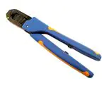
Hand Crimping Tool 90327-1 (shown in Figure 1) is
used to crimp Type VI Multimate contacts listed in
Figure 2 onto wire sizes 22 through 18 AWG with an
insulation diameter range of 1.27 through 2.79 [.050
through .110]. Read these instructions thoroughly
before crimping any contacts.
Typical Type VI
Multimate Contacts
Locator
Slot
Pin
Figure 1
NOTE
i
Dimensions on this instruction sheet are in metric
units [with inches in brackets]. Figures are not
drawn to scale.
Socket
Reasons for reissue of this instruction sheet are
provided in Section 7, REVISION SUMMARY.
2. DESCRIPTION
The tool features two fixed dies (crimpers), two
moving dies (anvils), insulation crimp adjustment
lever, contact support, locator/insulation stop, ejector,
and CERTI-CRIMP tool ratchet. When mated, the dies
form two crimping chambers.
© 2012 Tyco Electronics Corporation, a TE Connectivity Ltd. company
All Rights Reserved
*Trademark
4.37 [.172] Wire
Strip Length
Insulation
Barrel
WIRE
Wire
Barrel
CONTACT
SIZE
RANGE
(AWG)
INSUL.DIA
LOOSE
PIECE
STRIP-FORM
22-18
1.27-2.79
[.050-.110]
66591-[ ] (Pin)
66592-[ ] (Skt)
66581-[ ] (Pin)
66582-[ ] (Skt)
TOOLING ASSISTANCE CENTER 1-800-722-1111
PRODUCT INFORMATION 1-800-522-6752
Figure 2
This controlled document is subject to change.
For latest revision and Regional Customer Service,
visit our website at www.te.com
TE Connectivity, TE connectivity (logo), and TE (logo) are trademarks. Other logos, product and/or company names may be trademarks of their respective owners.
1 of 4
�408-7716
Back of Tool
(Wire Side)
Contact Support
Wire Size Marking
Mating End of Contact
Contact Wire Barrel Against
Locator/Insulation Stop
Crimpers
Wire Slot in Locator
Stripped Wire
Locator/Insulation
Stop Entering Contact
Locator Slot
Anvils
Figure 3
NOTE
i
If using strip-form contact, the cutoff tabs MUST
meet the dimension requirement stated on the
customer drawing for the product or Application
Specification 114-10007.
Proceed as follows:
1. Hold tool so BACK side (wire side) faces you.
2. Ensure that the tool ratchet is released by
squeezing tool handles and allowing them to open.
Crimp Inspection
Wire Conductor Must Be Flush
with or Protrude Slightly from
Wire Barrel
Contact Must Be
Straight
3. Insert contact, mating end first, into the crimping
chamber from the BACK of tool. Position contact
between crimpers so that the locator/insulation stop
enters the contact locator slot. Make sure that the
wire barrel butts against the locator/insulation stop.
See Figure 3.
4. Holding the contact in position, squeeze the tool
handles together until insulation barrel anvil starts
entry into the insulation crimper. Do NOT deform
contact insulation barrel or wire barrel.
5. Insert a properly stripped wire through the wire
slot in the locator and into the contact wire barrel
until the wire insulation butts against the locator/
insulation stop.
6. Holding the wire in place, squeeze the tool
handles together until the ratchet releases. Allow
tool handles to open FULLY.
7. Remove crimped contact from tool, and inspect
the crimp according to Figure 4.
Rev D
Wire Barrel Seam Must Be Closed
with No Wire Strands Showing
Wire Insulation Must
Be Visible in This Area
Locking Lance Must
Not Be Deformed
Figure 4
NOTE
For detailed crimp inspection requirements, refer to
Application Specification 114-10007.
i
4. INSULATION CRIMP ADJUSTMENT
The insulation barrel crimp height is regulated by the
insulation crimp adjustment lever. To determine the
proper setting, test crimp a contact using the setting
which approximates the wire insulation size: 1-small,
2-medium, or 3-large. If the crimped insulation barrel
is too tight or too loose, change the setting
accordingly. The crimp should hold the wire insulation
firmly without cutting into it.
2 of 4
�408-7716
5. MAINTENANCE AND INSPECTION
B. Crimp Height Inspection
The tool is inspected before shipment. It is
recommended that the tool be inspected immediately
upon arrival at your facility to ensure that the tool was
not damaged during shipment and that it conforms to
the dimensions provided in Figure 6.
Refer to Figure 5.
5.1. Daily Maintenance
1. Remove all foreign particles with a clean, soft
brush, or a clean, soft, lint-free cloth. Make sure the
proper retaining pins are in place, and secured with
the proper retaining rings. If foreign matter cannot
be removed easily, or if the proper replacement
parts are needed, refer to Section 6,
REPLACEMENT AND REPAIR.
2. Make certain all pivot points and bearing surfaces
are protected with a THIN coat of any good SAE 20
motor oil. Do NOT oil excessively.
3. When tool is not in use, keep the handles closed
to prevent objects from becoming lodged between
the crimping dies, and store the tool in a clean, dry
area.
Crimp height inspection is performed through the
use of a micrometer with a modified anvil,
commonly referred to as a crimp height comparator.
TE does not market crimp height comparators.
Refer to Instruction Sheet 408-7424 for detailed
information on obtaining and using a crimp height
comparator.
To measure the crimp height, proceed as follows:
1. Select a contact and maximum size wire for the
tool.
2. Refer to Section 3, CRIMPING PROCEDURE,
and crimp the contact accordingly.
3. Using a crimp height comparator, measure wire
barrel crimp height as shown in Figure 5. If the
crimp height conforms to that shown, the tool is
considered dimensionally correct. If not, refer to
Section 6 for information on obtaining evaluation
and repair.
5.2. Periodic Inspection
Regular inspections should be performed by quality
control personnel. A record of scheduled inspections
should remain with the tool and/or be supplied to
personnel responsible for the tool. Though
recommendations call for at least one inspection a
month, the inspection frequency should be based on
the amount of use, ambient working conditions,
operator training and skill, and established company
standards. These inspections should be performed in
the following sequence:
A. Visual Inspection
1. Remove all lubrication and accumulated film by
immersing the tool (handles partially closed) in a
suitable commercial degreaser that will not affect
paint or plastic material.
2. Make certain all retaining pins are in place and
secured with retaining rings. If replacements are
necessary, refer to Section 6.
CAUTION Do NOT remove the retaining pins as permanent
damage to the tool may result.
!
3. Close the tool handles until the ratchet releases,
then allow the tool handles to open freely. If handles
do not open quickly and fully, the spring is defective
and must be replaced (refer to Section 6,
REPLACEMENT AND REPAIR).
4. Inspect the head assembly, with special
emphasis on checking for worn, cracked, or broken
dies. If damage to any part of the head assembly is
evident, refer to Section 6.
Rev D
Spindle
Modified
Anvil
“A"
±0.05 [.002]
CONTACT
NUMBER
WIRE SIZE,
AWG (MAX)
CRIMP SECT
(WIRE SIZE
MARKING)
CRIMP
HEIGHT DIM.
“A"
66591
66592
22
22
0.94 [.037]
66591
66592
18
18-20
1.12 [.044]
Figure 5
C. Ratchet Inspection
Obtain a 0.0254 [.001] shim that is suitable for
checking the clearance between the bottoming
surfaces of the dies. Proceed as follows:
1. Select a contact and maximum wire size for the
tool.
2. Position the contact and wire between the dies,
according to Section 3, CRIMPING PROCEDURE.
Holding the wire in place, squeeze the tool handles
together until the ratchet releases. Hold the tool
3 of 4
�408-7716
handles in this position, maintaining just enough
pressure to keep the dies closed.
3. Check the clearance between the bottoming
surfaces of the dies. If the clearance is 0.0254
[.001] or less, the ratchet is satisfactory. If clearance
exceeds 0.0254 [.001] the ratchet is out of
adjustment and must be repaired (see Section 6,
REPLACEMENT AND REPAIR).
If the tool conforms to these inspection procedures,
lubricate it with a THIN coat of any good SAE 20 motor
oil, and return it to service.
replacement parts through your representative, or call
1-800-526-5142, or send a facsimile of your purchase
order to 717-986-7605, or write to:
CUSTOMER SERVICE (038-035)
TYCO ELECTRONICS CORPORATION
PO BOX 3608
HARRISBURG PA 17105-3608
For customer repair service, call 1-800-526-5136.
7. REVISION SUMMARY
Since the previous version of this document, the
following changes were made:
6. REPLACEMENT AND REPAIR
Customer-replaceable parts are listed in Figure 6. A
complete inventory should be stocked and controlled
to prevent lost time when replacement of parts is
necessary. Parts other than those listed should be
replaced by TE to ensure quality and reliability. Order
• Corrected document name op top of each page.
• Corrected table content in Figure 6.
• Updated document format.
2
REPLACEMENT PARTS
ITEM
PART NUMBER
DESCRIPTION
QTY PER
TOOL
1
21045-3
RING, Retaining
4
2
21045-9
RING, Retaining
2
Figure 6
Rev D
4 of 4
�