Instruction Sheet
Seating Tools 91312-[ ] and 91313-[ ]
For Z-PACK* HS3 Backplane Header
with ACTION PIN* Contacts
408-4546
22 NOV 11 Rev B
Seating Tool
BACKPLANE HEADER
SEATING
TOOL
POSITION
91312-1
50
91312-2
1000
91313-1
30
91313-2
60
ROWS
10
6
Typical Z-PACK HS3
Backplane Header
Printed Circuit
(PC) Board
ACTION PIN Contact
(PC Board Retention
Feature)
PC Board Support (Ref,
Customer Supplied)
Figure 1
1. INTRODUCTION
Seating Tools 91312-[ ] and 91313-[ ] are used to seat
Z-PACK HS3 backplane headers with ACTION PIN
contacts to allow solderless pc board installation.
NOTE
i
All dimensions on this document are in metric units
[with U.S. customary units in brackets].
Read these instructions and understand them before
using the seating tool.
Reasons for reissue of this instruction sheet are
provided in Section 7, REVISION SUMMARY.
2. DESCRIPTION
Each seating tool is an assembly of plates, bars, and
an adapter to seat the different sizes of the backplane
headers. Figure 1 lists a cross-reference of the
backplane header size to the seating tool part number
to be used.
© 2011 Tyco Electronics Corporation, a TE Connectivity Ltd. Company
All Rights Reserved
*Trademark
During seating, the seating tool sits inside the header
housing engaging the housing floor and contact
shoulders, preventing the contacts from pushing out of
the housing.
3. REQUIREMENTS
3.1. Application Tooling
Power for the seating tool must be provided by an
application tool (with a ram) capable of supplying a
downward force of 89 N [20 lb] per contact.
Manual Electric Servo Presses (CMP 6T) 1585699-8
and (CMP 12T) 1585698-8, and Bench Top Electric
Servo Press (CBP 5T) 1585696-9 are available for this
seating tool.
For information on the presses, visit the press-fit
assembly equipment website at
http://tooling.te.com/pressfit.asp.
TOOLING ASSISTANCE CENTER 1-800-722-1111
PRODUCT INFORMATION 1-800-522-6752
This controlled document is subject to change.
For latest revision and Regional Customer Service,
visit our website at www.te.com
TE Connectivity, TE connectivity (logo), and TE (logo) are trademarks. Other logos, product and/or Company names may be trademarks of their respective owners.
1 of 3
LOC B
�408-4546
3.2. PC Board Support Fixture (Customer Supplied)
A pc board support must be used to provide proper
support for the pc board and alignment of the seating
tool to the header, and to protect the pc board and
header contacts from damage. Design a pc board
support fixture using the recommendations in
Instruction Sheet 408-6927.
5. Center the seating tool and header under the
applicator ram of the applicator; slowly lower the
ram until it just meets the seating tool. Verify the
alignment of the pc board support, pc board,
header, and seating tool.
CAUTION
!
4. SEATING
1. Set the seating height to the dimension shown in
Figure 2 (applicator shut height will equal the
seating height PLUS the combined thicknesses of
the pc board and pc board support).
2. Position the header onto pc board so that the
header contact posts are properly aligned with the
holes in the pc board and pc board support.
3. Insert the header onto the pc board until the post
sections of the contacts are resting securely on, but
have not fully entered, the pc board.
For Seating Tools -1 (not keyed), make sure that
the grounding arrow is pointing toward the end row
of ground blades of the header.
NOTE
i
6. Cycle the applicator. Check the header for proper
seating using the requirements in the Application
Specification 114-13020.
7. Remove the pc board with the seated header or
reposition the pc board and pc board support to
seat additional headers.
CAUTION
!
4. Position the appropriate seating tool into the
header, making sure that the seating tool is
bottomed on the housing floor.
Damage to the pc board, seating tool, or header
may occur if the wrong size seating tool is used, the
seating height is improperly set, the grounding
arrow (for Seating Tools -1) is oriented incorrectly,
or the seating tool is not properly seated in the
header before cycling the ram.
Do not use damaged or defective headers.
5. MAINTENANCE AND INSPECTION
5.1. Initial Inspection
Each seating tool is assembled and inspected before
shipment. It is recommended that the seating tool be
inspected using Figure 3 immediately upon arrival to
ensure that it has not been damaged during shipment.
Applicator Ram
(Fully Down) (Ref)
Seating Tool Centered
Under Ram
Seating Height
(Header Seated)
38.1 +.254/-0.00
[1.500 +.010/-.000]
Applicator
Shut Height
(Ram Down)
Seating Tool Inside Header
Housing and Bottomed on
Housing Floor
0.00-0.254 [.000-.010]
(Single Plane Application)
0.10 [.004] Max
(Mid-Plane Application)
Allowable Gap
Contact Posts Aligned with Holes in
PC Board and PC Board Support
PC Board
PC Board Support
Figure 2
Rev B
2 of 3
�408-4546
5.2. Daily Maintenance
6. REPLACEMENT AND REPAIR
It is recommended that each operator be made aware
of, and responsible for, the following steps of daily
maintenance:
The parts listed in Figure 3 are customer-replaceable.
A complete inventory can be stocked and controlled to
prevent lost time when replacement of parts is
necessary. Order replacement parts through your
Representative, or call 1-800-526-5142, or send a
facsimile of your purchase order to 1-717-986-7605 or
write to:
1. Remove dust, moisture, and other contaminants
with a clean, soft brush, or lint-free cloth. Do NOT
use objects that could damage the tool or any of its
components.
CUSTOMER SERVICE (038-035)
TYCO ELECTRONICS CORPORATION
PO BOX 3608
HARRISBURG PA 17105-3608
2. Ensure that pins and screws are in place and
secured.
3. When the seating tool is not in use, store it in a
clean, dry area.
For customer repair service, call 1-800-526-5136.
5.3. Periodic Inspection
Regular inspections should be performed by quality
control personnel. A record of scheduled inspections
should remain with the seating tool or be supplied to
supervisory personnel responsible for the seating tool.
The inspection frequency should be based on the
amount of use, working conditions, operator training
and skill, and established company standards.
7. REVISION SUMMARY
Revisions to this instruction sheet include:
• Changed company name and logo
• Changed Paragraph 3.1
• Replaced reference to application specification
• Added gap for mid-plane application to Figure 2
50.8 [2.00]
38.1 [1.50]
1
3
2
4
5
6
12.45 [.490] (Seating Tools -1)
24.92 [.981] (Seating Tools -2)
10 Rows
91312-1
12.01 [.473]
Note: Seating Tool 91313-2 shown
PART NUMBER FOR SEATING TOOL
ITEM
7
QTY PER SEATING TOOL
6 Rows
91312-2
91313-1
DESCRIPTION
91312-[ ]
91313-[ ]
1
1
2 (-1) 4 (-2)
2 (-1) 4 (-2)
Slotted Spring Pin
1
1
91313-2
1
1320190-1
1320190-1
Adapter
2
2-21012-8
2-21012-8
Socket Set Screw, 6-32×.19 in.
3
1-21028-0
21028-6
4
1320192-1
1320192-2
1320193-1
1320193-2
Signal Pin Bar
1
1
5
1320194-1
1320194-2
1320194-1
1320194-2
Ground Pin Drive Bar
4
2
1320195-1
—
1320196-1
1320196-2
Side Plate
2
2
—
1320195-2
—
—
Side Plate
1
—
—
1583844-1
—
1583646-1
Side Plate, Keyed
1
1
6
7
Figure 3
Rev B
3 of 3
�
很抱歉,暂时无法提供与“91312-1”相匹配的价格&库存,您可以联系我们找货
免费人工找货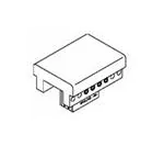


 工商网监
湘ICP备2023018690号
工商网监
湘ICP备2023018690号
