Instruction Sheet
Seating Tools 91347-[ ], 91350-[ ], and
91376-[ ] for Z-PACK* Hard Metric
(HM)-Zd Receptacle Connectors
408-8500
26 JUN 14 Rev G
ORIGINAL INSTRUCTIONS
Seating Tool 91376-1
(Shown)
HM-Zd 2-Pair Receptacle
Connector (Shown)
Printed Circuit
(PC) Board
Eye-Of-Needle
Contacts
SEATING
TOOL
CONNECTOR
TYPE
91350-[ ]
2-pair
91376-[ ]
3-Pair
91347-[ ]
4-Pair
PC Board Support Fixture
(Customer Designed)
Figure 1
1. INTRODUCTION
Seating Tools 91347-[ ], 91350-[ ], and 91376-[ ] are used to seat Z-PACK HM-Zd receptacle connectors onto a
pc board. See Figure 1. Dash number indicates number of connector columns. The connectors contain eye-ofneedle contacts which allow solderless pc board installation.
NOTE
All numerical values in this instruction sheet are in metric units [with U.S. customary units in brackets]. Dimensions are in
millimeters [and inches]. Figures are not drawn to scale.
Read these instructions and understand them before using the seating tool.
Reasons for reissue of this instruction sheet are provided in Section 7, REVISION SUMMARY.
2. DESCRIPTION
The seating tool is a one-piece design. During seating, the seating tool covers the connector and presses on
the top surface of the connector when the applicator ram applies force to the seating tool.
3. REQUIREMENTS
3.1. PC Board Support Fixture (Custom Designed)
A pc board support must be used to provide proper support for the pc board and alignment of the tool to the
contacts and to protect the pc board and contacts from damage.
3.2. Application Tooling
Power for seating tools must be provided by a machine capable of supplying a downward force of 89 Newtons
(N) [20 lb.] per contact. Manual Electric Servo Press (MEP 6T) 1585699-1, Bench Top Electric Servo Presses
(BMEP 3T) 1585697-1, and (BMEP 5T) 1585696-1 are available for this seating tool. For information on the
presses, visit the press-fit assembly equipment website at http://tooling.te.com/pressfit.asp.
© 2014 TE Connectivity family of companies
All Rights Reserved
*Trademark
TOOLING ASSISTANCE CENTER 1-800-722-1111
PRODUCT INFORMATION 1-800-522-6752
This controlled document is subject to change.
For latest revision and Regional Customer Service,
visit our website at www.te.com.
TE Connectivity, TE connectivity (logo), and TE (logo) are trademarks. Other logos, product, and/or company names may be trademarks of their respective owners.
1 of 4
�408-8500
CAUTION
Over-driving of the connector will deform parts critical to the quality of the connection. Maximum force occurs prior to the
connector bottoming on the pc board.
4. SEATING
1. Set seating height to the dimension shown in Figure 2 (application tool shut height will equal the tool
seating height PLUS the combined thicknesses of the pc board and support fixture). After seating, a
gap of no more than 0.10 mm [.004 in.] between the connector housing and the pc board is allowed.
NOTE
The seating height of 38.1 mm [1.50 in.] is a reference starting point. The seating height might have to be adjusted to properly
seat the connector onto the pc board.
2. Position the connector on the pc board so that contacts are properly aligned with the holes in the pc
board and pc board support fixture.
3. Sit the connector onto pc board until the open section of the contacts are resting securely on, but have
not fully entered, the holes in the pc board.
4. Position the seating tool onto the connector.
5. Center the seating tool (with the connector) under the ram of the applicator tool; slowly lower the ram
until it just meets the seating tool. Verify the alignment of the pc board support fixture, pc board,
connector, and seating tool.
CAUTION
Damage to the pc board, seating tool, or connector may occur if the seating height is improperly set, the pc board is not
properly positioned over the pc board support, or the seating tool is not properly seated on the connector before cycling the
applicator ram.
6. Cycle the ram according to instructions included with the application tooling. Check the connector for
proper seating using the requirements in Application Specification 114-13059.
7. Remove the pc board or re-position the pc board and pc board support fixture for seating additional
connectors.
View After Seating
NOTE: Not to Scale
Applicator Ram
(Fully down)
Seating Height
(Connector Seated)
38.1 [1.50] Ref
Applicator Tooling
Shut Height
(Ram Down)
Seating Tool Centered
Under Applicator Ram and
Bottomed on Connector
Maximum Gap
Allowed
0.10 [.004]
Contacts in PC Board Holes
and Aligned with Holes in PC
Board Support Fixture
PC Board
PC Board Support Fixture
Figure 2
Rev G
2 of 4
�408-8500
5. MAINTENANCE AND INSPECTION
It is recommended that each operator be made aware of, and responsible for, the following steps of daily
maintenance:
1. Remove dust, moisture, and other contaminants with a clean, soft brush, or lint-free cloth. DO NOT
use objects that could damage the tool or any of its components.
2. Ensure that the screws are in place and secured.
3. When the tool is not in use, store it in a clean, dry area.
Each seating tool is assembled and inspected before shipment. It is recommended that the tool be inspected
using Figure 3 immediately upon arrival to assure that it has not been damaged during shipment.
Regular inspections should be performed by quality control personnel. A record of scheduled inspections
should remain with the tool or be supplied to personnel responsible for the tool. The inspection frequency
should be based on the amount of use, working conditions, operator training and skill, and established
company standards.
6. REPLACEMENT AND REPAIR
Order replacement seating tools through your local TE Connectivity Representative, or call 1-800-526-5142, or
send a facsimile of your purchase order to 717-986-7605, or write to:
CUSTOMER SERVICE (038-035)
TYCO ELECTRONICS CORPORATION
PO BOX 3608
HARRISBURG PA 17105-3608
7. REVISION SUMMARY
Updated document to corporate requirements
Added new part numbers (91350-3, -4) and related information to table in Figure 3
Seating Tool 91347-[ ] (4-Pair Connector)
25.4
[1.00]
22.5
[.884]
4.44 [.175]
(F Places)
33.0 [1.30]
A
D
B
E
C
SEATING TOOL
91347-1
91347-2
91347-3
91347-4
91347-5
A
5.46 [.215]
5.21 [.205]
5.26 [.207]
5.18 [.204]
5.38 [.212]
B
15.49 [.610]
27.69 [1.090]
20.24 [.797]
15.19 [.598]
---
DIMENSION
C
25.4 [1.00]
37.34 [1.470]
29.97 [1.180]
49.78 [1.960]
12.70 [.500]
D
------30.18 [1.188]
---
E
------40.18 [1.582]
---
F
2
2
2
4
1
Figure 3 (cont’d)
Rev G
3 of 4
�408-8500
Seating Tool 91350-[ ] (2-Pair Connector)
29.5
[1.163]
32.3
[1.27]
19
[.750]
4.44 [.175]
(F Places)
A
24.1
[.950]
B
D
E
C
DIMENSION
SEATING TOOL
F
A
B
C
D
E
91350-1
5.46 [.215]
15.49 [.610]
25.4 [1.00]
---
---
2
91350-2
5.18 [.204]
15.19 [.598]
49.78 [1.960]
30.18 [1.188]
40.18 [1.582]
4
91350-3
5.25 [.207]
---
10.70 [.421]
---
---
1
91350-4
5.25 [.207]
---
14.90 [.587]
---
---
1
Seating Tool 91376-[ ] (3-Pair Connector)
26.97
[1.062]
29.97
[1.180]
4.44 [.175]
(2 Places)
A
28.58
[1.125]
B
C
SEATING TOOL
DIMENSION
A
B
C
91376-1
5.46 [.215]
15.49 [.610]
25.4 [1.00]
91376-2
5.18 [.204]
15.19 [.598]
49.78 [1.960]
Figure 3 (end)
Rev G
4 of 4
�
很抱歉,暂时无法提供与“91350-1”相匹配的价格&库存,您可以联系我们找货
免费人工找货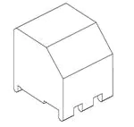


 工商网监
湘ICP备2023018690号
工商网监
湘ICP备2023018690号
