Instruction Sheet
408-8582
SDE Criming Die Assembly 91912-[ ]
21 NOV 11 Rev A
PROPER USE GUIDELINES
Cumulative Trauma Disorders can result from the prolonged use of manually powered hand tools. Hand tools are intended for occasional use
and low volume applications. A wide selection of powered application equipment for extended-use, production operations is available.
crimps the center contact onto the center conductor of
the coaxial cable. Each die is held in the
PRO-CRIMPER II hand tool jaws by a single screw.
Indenter
Die
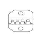
3. DIE INSTALLATION (Figure 1)
1. Close the tool handles until the ratchet releases,
then allow the tool handles to open fully.
Ferrule
Crimping
Chamber
Typical
Crimping Die
Assembly
2. Install anvil die in the movable jaw of the tool
frame. Align the die with the retaining screw hole,
then secure die with the die-retaining screw. Do
NOT fully tighten.
3. Install indenter die in the stationary jaw of the tool
frame. Slowly close the tool handles, allowing the
dies to align themselves.
NOTE
Anvil
Die
i
Center Contact
Crimping Chamber
Once the anvil has entered the indenter, place a
copper bus bar (1.57-mm ± 0.05 mm
[.062-in. ± .002 in.] diameter) into the center
contact crimping chamber of the die assembly.
4. Close the tool handles completely.
5. Securely tighten both screws with the appropriate
screwdriver.
Figure 1
1. INTRODUCTION
4. CRIMPING PROCEDURE
SDE (Four-Piece) Crimping Die Assemblies 91912-[ ]
are designed to crimp a variety of connectors when
used in PRO-CRIMPER* II Hand Tool Frame
Assembly 354940-1. Refer to Figure 5 for a list of
connectors and their associated dies, as well as
detailed drawings of the crimping dies.
Select the appropriate cable size and connector. The
wire size and insulation diameter must be within the
specified range for the connector.
Catalog 1307191 provides a guide for cable- toconnector selection. For connectors not referenced in
the catalog, contact TE Product Engineering for
recommendations.
Refer to instruction sheet 408-9930 for information
concerning PRO-CRIMPER II Hand Tool Frame
354940-1.
NOTE
Dimensions in this document are in metric units
[with U.S. customary units in brackets].
i
2. DESCRIPTION
Each four-piece crimping die assembly consists of two
indenter dies and two anvil dies, which when closed
form two or three crimping chambers. The larger
crimping chambers crimp the ferrule of the connector
onto the coaxial cable. The smaller crimping chamber
© 2011 Tyco Electronics Corporation, a TE Connectivity Ltd. Company
All Rights Reserved
*Trademark
NOTE
i
This tool is provided with a crimp height adjustment
feature. Initially, the crimp height should be verified.
Refer to Section 5, Crimp Height Adjustment, to
verify crimp height before using the tool.
For detailed information on cable strip lengths and
proper assembly of the connector, refer to the
instructions packaged with the connector. Make sure
that the connector's ferrule has been placed onto the
cable, and that the cable's braided shield is flared
away from the cable. Then proceed as follows:
4.1. Crimping the Center Contact (Figure 2)
1. Close the tool handles until the dies are partially
closed.
2. Assemble the center contact onto the cable
center conductor and place the center contact in the
smallest crimping chamber of the anvil die. Make
sure the flange on the end of the center contact
butts against the die.
TOOLING ASSISTANCE CENTER 1-800-722-1111
PRODUCT INFORMATION 1-800-522-6752
This controlled document is subject to change.
For latest revision and Regional Customer Service,
visit our website at www.te.com
TE Connectivity, TE connectivity (logo), and TE (logo) are trademarks. Other logos, product and/or Company names may be trademarks of their respective owners.
1 of 4
LOC B
�408-8582
Cross Sectional View
Crimping the Center Contact
Flange on
End of Contact
Plug
Contact
Crimping
Die
Center Contact in
Crimping Chamber
Jack
Contact
Flange on
End of Contact
Anvil Die
Stripped
Cable
Crimping
Die
Figure 2
3. Holding the cable in place, close the tool handles
until the ratchet releases.
4. Allow the tool handles to open fully and remove
the crimped center contact from the dies.
4.2. Crimping the Ferrule (Figure 3)
1. Insert the crimped center contact into the
connector body until the cable dielectric butts
against the dielectric inside the connector body or
until the center contact is securely positioned within
the connector. Make sure that the braided shield is
over the support sleeve of the connector body and
that no strands from the shield enter the connector
body.
CAUTION Make sure that both sides of the ferrule are started
evenly into the crimping chamber. Do not attempt to
crimp an improperly positioned ferrule.
!
5. Carefully close the tool handles until the ratchet
releases.
Crimping the Ferrule
Shoulder on
Connector Body
Butts Against the
Edge of the Die
2. Slide the ferrule up over the braided shield and
onto the connector until the ferrule butts against the
shoulder on the connector body.
3. Place the ferrule in the appropriate crimping
chamber of the anvil die so that the shoulder on the
connector body butts against the edge of the die.
NOTE
i
Refer to the instruction sheet packaged with the
connector to determine the appropriate crimping
chamber for the ferrule.
4. While holding the assembly together, begin to
close the tool handles. Keep holding the assembly
until the dies have closed enough to clamp the
assembly in place.
Rev A
Ferrule in
Crimping
Chamber on
Anvil Die
Figure 3
2 of 4
�408-8582
6. Allow the tool handles to open fully and remove
the crimped connector from the dies.
Screwdriver
5. CRIMP HEIGHT ADJUSTMENT
The tool frame assembly ratchet mechanism features
an adjustment wheel with numbered settings. If the
crimp height is not acceptable, adjust the ratchet as
follows:
Lockscrew
(Typ)
1. Remove the lockscrew from the ratchet
adjustment wheel.
2. With a screwdriver, adjust the ratchet wheel from
the opposite side of the tool.
3. Observe the ratchet adjustment wheel. If a tighter
crimp is required, rotate the adjustment wheel
COUNTERCLOCKWISE to a higher-numbered
setting. If a looser crimp is required, rotate the
adjustment wheel CLOCKWISE to a lowernumbered setting.
4. Replace the lockscrew.
5. Make a sample crimp and measure the crimp
height. If the crimp height is acceptable, secure the
lockscrew. If the dimension is unacceptable, remove
lockscrew and continue to adjust the ratchet, and
again measure a sample crimp.
6. MAINTENANCE AND INSPECTION
6.1. Maintenance
1. Remove dust, moisture, and other contaminants
with a clean, soft brush, or a clean, soft, lint-free
cloth. Do NOT use any objects that could damage
the dies or tool.
2. Make sure that the proper die-retaining screws
are properly secured.
3. When the dies are not in use, store them in a
clean, dry area.
4. Store the tool with the tool handles closed to
prevent objects from becoming lodged within the
jaws.
6.2. Inspection
1. Remove all lubrication and accumulated film from
the dies by immersing the dies in a suitable
commercial degreaser.
Ratchet
Adjustment
Wheel
Figure 4
6.3. Measuring the Die Opening
The die assembly will perform correctly as long as:
(1) the product specified is correct for the application,
(2) the specific die assembly is used, (3) the die
assembly has been measured to ensure that the
openings are correct, and (4) the tool has been
adjusted correctly. Figure 5 provides information on
die opening sizes.
7. REPLACEMENT
These crimping die assemblies are inspected before
shipment. It is recommended that the dies be
inspected immediately upon arrival at your facility to
ensure that the dies have not been damaged during
shipment.
Order replacements through your local TE
representative, or call 1-800-526-5142, or send a
facsimile of your purchase order to 1-717-986-7605, or
write to:
CUSTOMER SERVICE (038-035)
TYCO ELECTRONICS CORPORATION
PO BOX 3608
HARRISBURG PA 17105-3608
8. REVISION SUMMARY
Revisions to this instruction sheet include:
• Changed company name and logo
2. Make certain that all die-retaining screws and die
components are properly secured.
3. Inspect the crimping surfaces for flattened,
chipped, worn, or cracked areas. If damage is
evident, the dies must be replaced. Refer to
Section 7, REPLACEMENT.
Rev A
3 of 4
�408-8582
B ± 0.05
A ± 0.025
C ± 0.05
Die 91912-[ ]
PART NUMBER
DIE CLOSURE DIMENSIONS (MM [IN.])
PRODUCT DESCRIPTION
A
B
C
91912-1
Miniature Threaded COAXICON Connectors
0.472 [.0186]
2.030 [.079]
3.53 [.139]
91912-2
Miniature Threaded COAXICON Connectors
0.472 [.0186]
2.340 [.092]
3.53 [.139]
91912-3
Miniature COAXICON Connectors
0.965 [.038]
2.900 [.114]
3.61 [.142]
91912-4
Miniature COAXICON Connectors
0.965 [.038]
2.870 [.113]
3.53 [.139]
91912-5
Miniature COAXICON Connectors
0.965 [.038]
6.81 [.268]
5.16 [.203]
Figure 5
Rev A
4 of 4
�


 工商网监
湘ICP备2023018690号
工商网监
湘ICP备2023018690号
