CV-OBHAT-SIL-ARM-GRIP 数据手册
APPLICATION
TOOLING
FOR RAYCHEM HEAT SHRINK PRODUCTS
FROM TE CONNECTIVITY
TE APPLICATION TOOLING /// RAYCHEM HEAT SHRINK PRODUCTS
�APPLICATION TOOLING
FOR RAYCHEM HEAT SHRINK PRODUCTS
AD-3050 Seal Test Equipment
Sealing Evaluation – Various Products
Product Features
Ordering Information
• Fast determination of sealing integrity
• AD-3050-SEAL-TEST-EQ-NC
• Multiple test fixtures
PN: C82893-000
• Easy load and release of test samples
• Version with integrated timer:
• Connector seal test port
AD-3050-SEAL-TEST-EQ-NC-TIMER
• �Timer adjustable from 8 – 120 seconds
PN: 528024-1
(only with integrated AD-3050 Seal Test Equipment
(Timer retrofit kit available)
timer version)
Accessories
Technical Data
• Recommended spares
• Pneumatic supply:
Set of 8 Seals**
600 kPa / 6 bar maximum, filtered supply
AD-3050-SEAL-8-KIT
200 kPa / 2 bar test pressure maximum
PN: 299155-000
(Test pressure typically 50 kPa / 0.5 bar)
• Clamp assembly including seals
• Machine cycle times for seal testing: Typically 1 min.
AD-3050-SEAL-CLAMP-ASSY
• Total system noise: Negligible noise from air test
PN: 168927-000
• Dimensions: 550 x 350 x 215 mm (21.7 x 13.8 x 8.5 in)
• Sealing tape
(excludes packing case)
EPDM foam, 6 x 9 mm, with acrylic adhesive backing
• Weight: 4 kg (excludes packing case)
** Full set of seals
As the equipment is designed to use readily available pneumatic
components, these are listed on the parts list which is included with
the equipment.
TE APPLICATION TOOLING /// RAYCHEM HEAT SHRINK PRODUCTS
PAGE 2
�The AD-3050 seal test equipment is a manually
The test result is determined visually by looking for
operated pneumatic device, intended for use as a
bubbles in the area of the sealing product. Connectors
convenient “in process” sampling technique for
can also be pressure tested by adapting the separate
checking sealed splices.
supply fixture to any connector type. Use of this
Different combinations of in-line, end-/stub-splices
equipment is described in TE’s customer manual. This
and various ring terminal applications can be pressure
tested in any of the combination of fixtures (8 in total).
There is also a facility to allow leak testing of various
connectors. The tool is also intended for use as a quick
equipment can also check for poke through i.e. where
individual wire strands poke through the installed heat
shrinkable sleeve, by using any applicable measure
instruments.
and easy sampling technique for the preliminary
selection of installation conditions where Raychem
splice protection products are used.
TE has seen good correlation between results
obtained with the AD-3050 seal test and those
obtained through water immersion testing. However
testing in accordance with the Original Equipment
Manufacturer (OEM) specification is the only way of
confirming that the OEM specification is being met.
The splice products are located in clamps which
deliver the test pressure. The product is immersed in
water and pressure is delivered through the wire(s) to
the sealed area.
APPLICATION SAMPLES
TE APPLICATION TOOLING /// RAYCHEM HEAT SHRINK PRODUCTS
PAGE 3
�APPLICATION TOOLING
FOR RAYCHEM HEAT SHRINK PRODUCTS
RBK ILS Processor MK 4
Installation of Splice Sealing Products
Ultrasonic Welder
Product Features
• Long life heating elements
• Pre-installed connection for an optional
• Installation times, temperatures, and product size
air-cooling-device
information (individual selection)
• Second D-SUB-9-connector with a signal output
• Sequenced installations
“0” volt (n/c and n/o) where the machine can be
• Operator key lock/password protection levels
connected to a server, local PC or customer intranet
• Automatic heater retraction on mains failure
• Machine hours and installation cycle counters
(updated safety feature)
• Software upgradeable to support special
• Automatic calibration (single cycle)
applications
• RS232 interface allows time, temperature and
• �Integrated SW-safety-features to provide a high
product sizes for the next installation to be trans-
ferred from a remote machine (e.g. an ultrasonic
welding tool)
level of safety during processing
• Compliant with latest CE and RoHs requirements
• Big mechanical protection-cover (removable) in
front of the feeding-/working-area
APPLICATION SAMPLES
TE APPLICATION TOOLING /// RAYCHEM HEAT SHRINK PRODUCTS
PAGE 4
�Technical Data
The RBK ILS processor MK 4 is a semiautomatic unit
• Electrical supply: 220 – 240 V, 50 Hz
designed specifically to install splice sealing products
• Power consumption: 1.7 A (max.)
onto ultrasonically welded or crimped splice joints
• Operating temperature: 500 °C recommended
used in automotive harnesses.
• Machine cycle times for splice sealing products used
The tool can operate in several modes:
on typical range of automotive splices:
6 to 20 sec. depending on wire size and the number
or wires used
• Total system noise:
CV-OBHAT-SIL-ARM-GRIP 价格&库存
很抱歉,暂时无法提供与“CV-OBHAT-SIL-ARM-GRIP”相匹配的价格&库存,您可以联系我们找货
免费人工找货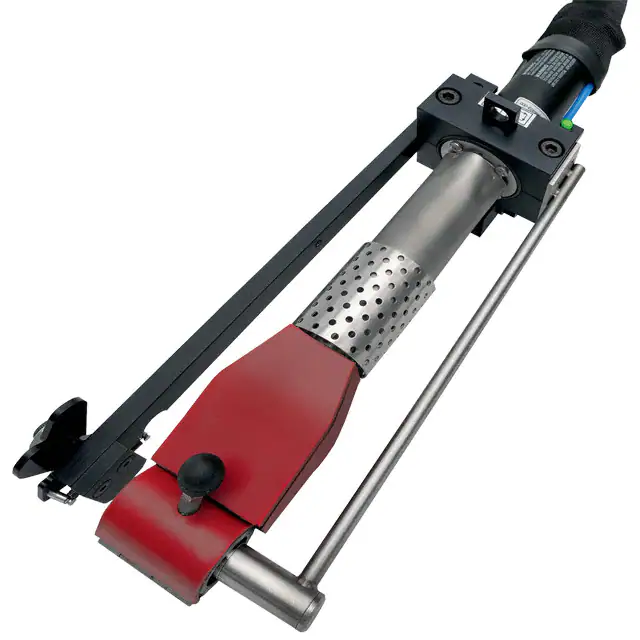


 工商网监
湘ICP备2023018690号
工商网监
湘ICP备2023018690号
