TSD305-2C55
DIGITAL TEMPERATURE SENSOR
Product Description
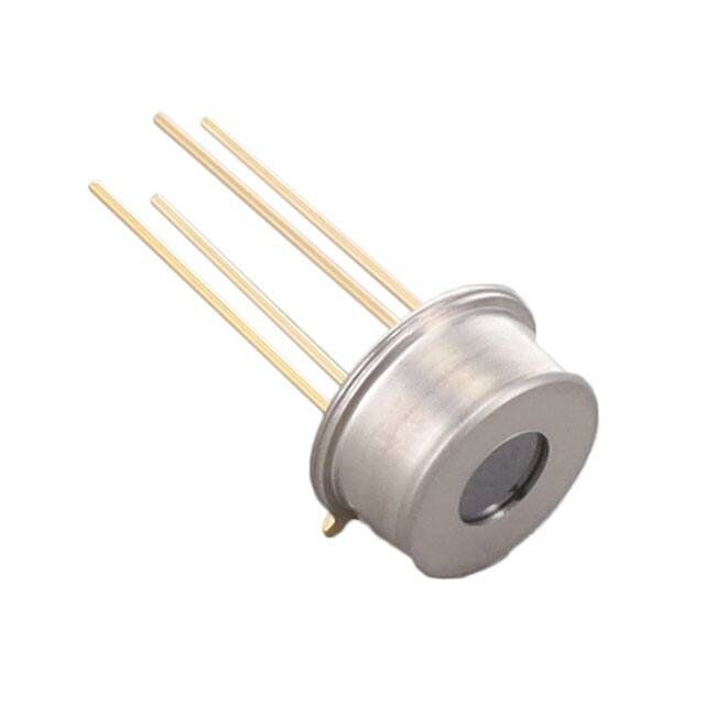
The TSD is a contactless temperature measurement system located in
a TO5 package. The TSD includes an infrared sensor (thermopile) and
a sensor signal conditioner.
The TSD can be interfaced to any microcontroller by an I2C interface.
This microcontroller has to calculate the temperature results based on
the ADC values and the calibration parameters
Features
0°C … +300°C measurement range
Small size
Low current consumption
I2C Interface
Operating Temperature Range: -10°C … +85°C
Applications
Contactless temperature measurement
Industrial process control
Climate control
Household applications
SENSOR SOLUTIONS /// DATASHEET TSD305-2C55
10/2016
Page 1
�TSD305-2C55
Digital Thermopile Sensor
ABSOLUTE MAXIMUM RATINGS
Absolute maximum ratings are limiting values of permitted operation and should never be exceeded under the worst possible
conditions either initially or consequently. If exceeded by even the smallest amount, instantaneous catastrophic failure can
occur. Even if the device continues to operate satisfactorily, its life may be considerably shortened.
Parameter
Symbol
Condition
Min
Typ
Max
Unit
Supply voltage
VDD
---
-0.3
---
+3.63
V
Storage temperature
Tstor
dry
-20
---
+85
°C
VDD VIO
---
-0.5
---
VDD +0.5
V
IIN
---
-100
---
100
mA
ESD rating
ESD
Human Body Model
-2
---
+2
kV
Humidity
Hum
---
Voltage at supply and IO pins
Current into supply and IO pins
Non condensing
---
OPERATING CONDITIONS
If not otherwise noted, 3.3V supply voltage is applied.
Parameter
Symbol
Condition
Min
Typ
Max
Unit
Operating supply voltage
VDD
stabilized, 100nF
1.68
---
3.6
V
VDD rise time
tVDD
---
---
---
200
µs
Operating temperature
Top
---
-20
---
+85
°C
Object temperature range
TOBJ
---
0
---
+300
°C
Resolution
RES
---
---
---
0.1
°C
Active state, average
---
1050
1500
µA
Supply Current
IVDD
Sleep state, idle current
---
20
25
nA
Serial data clock I2C
FSCL
---
---
---
3.4
MHz
Self heating
SH
1 sample/s, still air, 60s
---
---
+0.2
°C
CVDD
Place close to the sensor
---
100
---
nF
VDD capacitor
THERMOPILE COMPONENT
If not otherwise noted, 3.3V supply voltage is applied.
Parameter
Absorber area
Symbol
Condition
A
---
Min
Typ
Max
0.8 x 0.8
Unit
mm
At 50% of maximum signal
Field of view
FOV
Filter transmission range
LWP
SENSOR SOLUTIONS /// DATASHEET TSD305-2C55
---
Long wave pass
88
---
>5.5
deg
µm
10/2016
Page 2
�TSD305-2C55
Digital Thermopile Sensor
ANALOGUE TO DIGITAL CONVERTER
Parameter
Symbol
Condition
Min
Typ
Max
Unit
Resolution
ADCRES
---
---
16
---
bit
tCONV
---
---
44.8
59.2
ms
t63
Including rise time of sensor element
---
---
44.8
ms
ITSRES
---
---
0.003
---
K/LSB
Conversion time
Rise time
Resolution internal temperature
sensor
TOLERANCES
If not otherwise noted, 3.3V supply voltage is applied.
Parameter
Tsen = sensor temperature, Tobj = object temperature
Symbol
Sensor Temo
Object Temp
Max
Unit
Accuracy Standard Temp 1)
ACCS
+10°C < Tsen < +40°C
+170°C < Tobj < +190°C
±1.5
%FS
Accuracy Extended Temp. 2)
ACCE1
Complete range
Complete range
±2.5
%FS
Other temperature ranges and accuracies are available on request.
1) Proved while production
2) Proved by design
POWER & RESET
Parameter
Symbol
Condition
Min
Typ
Max
Unit
tSTA1
VDD ramp up to interface
communication
---
---
1
ms
tSTA2
VDD ramp to first ADC measurement
---
---
2.5
ms
tWUP1
Sleep to active state interface
communication
---
---
0.5
ms
tWUP2
Sleep to first ADC measurement
---
---
2
ms
tRESET
VDDlow
3
---
---
µs
VDD low level
VDDlow
---
0
---
0.2
V
VDD rising slope
SRVDD
---
10
---
---
V/ms
Start up time
Wake up time
Power down time for reset
DIMENSIONS
If not specified, all tolerances according DIN ISO 2768-m.
SENSOR SOLUTIONS /// DATASHEET TSD305-2C55
10/2016
Page 3
�TSD305-2C55
Digital Thermopile Sensor
PIN FUNCTION TABLE
Pin
Name
Type
Function
1
SCL
DI
I2C Clock
2
SDA
DIO
I2C Data
3
VDD
P
Supply Voltage
4
VSS
P
Ground
I2C INTERFACE
An I2C communication message starts with a start condition and it is ended by a stop condition.
Most commands consist of two bytes: the address byte and command byte.
I2C ADRESS
The standard I2C address is 0x00 (0b0000000X).
X = 0:
I2C Write
X = 1:
I2C Read
STATUS BYTE
Each return starts with a status byte followed by the requested data word.
Bit
7
6
5
4
3
2
1
0
Meaning
---
---
Busy
---
---
Memory
Error
---
---
Busy:
1 = Sensor is busy. The requested data is not available yet.
Memory Error:
1 = Memory integrity check failed. Memory was changed after factory calibration.
COMMANDS
Note: Each return starts with a status byte followed by the requested data word.
Command
Return
Description
16 bit EEPROM data
Read data from EEPROM address (0x00 … 0x39) matching
the command
24 bit object temperature ADC,
24 bit sensor temperature ADC
Measure object temperature and sensor temperature ADC 16
times and calculates mean value. Store data in output buffer.
0x00 … 0x39
0xAF
Read EEPROM
Write Command:
Read EEPROM Data:
SENSOR SOLUTIONS /// DATASHEET TSD305-2C55
10/2016
Page 4
�TSD305-2C55
Digital Thermopile Sensor
Perform Measurement and Read ADC Data
Write Command:
Read ADC Data:
EEPROM CONTENT
Example
Adress / hex
0x00
0x01
0x02 ... 0x19
0x1A
0x1B
0x1C
0x1D
0x1E
0x1F
0x20
0x21
0x22
0x23
0x24
0x25
0x26
0x27
0x28
0x29
0x2A
0x2B
0x2C
0x2D
0x2E
0x2F
0x30
0x31
0x32
0x33
0x34
0x35
0x36
0x37
0x38
Adress / dec
0
1
2 ... 25
26
27
28
29
30
31
32
33
34
35
36
37
38
39
40
41
42
43
44
45
46
47
48
49
50
51
52
53
54
55
56
Description
Name
Lot Nr.
Serial Number
Factory Calibration Data
Min. Sensor Temp. / °C
Max. Sensor Temp. / °C
Min. Object Temp. / °C
Max. Object Temp. / °C
TSenMin
TSenMax
TObjMin
TObjMax
Temperature Coefficient
TC
Reference Temperature
TREF
Compensation
Coefficient k4
Compensation
Coefficient k3
Compensation
Coefficient k2
Compensation
Coefficient k1
Compensation
Coefficient k0
Not used
ADC T
Coefficient k4
ADC T
Coefficient k3
ADC T
Coefficient k2
ADC T
Coefficient k1
ADC T
Coefficient k0
Status
SENSOR SOLUTIONS /// DATASHEET TSD305-2C55
-------
k4comp
k3comp
k2comp
k1comp
k0comp
--k4Obj
k3Obj
k2Obj
k1Obj
k0Obj
---
Format
UINT16
UINT16
--SINT16
SINT16
SINT16
SINT16
IEEE 754 H-Word
IEEE 754 L-Word
IEEE 754 H-Word
IEEE 754 L-Word
IEEE 754 H-Word
IEEE 754 L-Word
IEEE 754 H-Word
IEEE 754 L-Word
IEEE 754 H-Word
IEEE 754 L-Word
IEEE 754 H-Word
IEEE 754 L-Word
IEEE 754 H-Word
IEEE 754 L-Word
----IEEE 754 H-Word
IEEE 754 L-Word
IEEE 754 H-Word
IEEE 754 L-Word
IEEE 754 H-Word
IEEE 754 L-Word
IEEE 754 H-Word
IEEE 754 L-Word
IEEE 754 H-Word
IEEE 754 L-Word
UINT16
Content
Value
15001
12345
--0xFFEC
0x0055
0x0000
0x0064
0xBB96
0xBB99
0x41D7
0x70A4
0x3A07
0x4C8C
0x3F10
0x5CEC
0x4367
0x0D1F
0x4724
0x5A6F
0xC9A0
0x254D
----0x944B
0xD24F
0x2052
0xF1C2
0xABE5
0x991B
0x3797
0x2BBF
0x41D7
0x6DBA
TBD
YY WWW
Number
---20°C
+85°C
0°C
100°C
10/2016
-0.0046
26.93
5.161E-04
5.639E-01
2.311E+02
4.207E+04
-1.312E+06
---1.029E-26
1.787E-19
-1.631E-12
1.802E-05
2.693E+01
---
Page 5
�TSD305-2C55
Digital Thermopile Sensor
NUMBER FORMAT
UINT16
Description:
Bits
16
Min (dec/hec/bin)
0
Max (dec/hec/bin)
65,535 / 0xFFFF / 0b1111 1111 1111 1111
Description:
Signed integer
Bits
16
Min (dec/hec/bin) -
32,768 / 0x8000 / 0b1000 0000 0000 0000
Max (dec/hec/bin)
32,767 / 0x7FFF / 0b0111 1111 1111 1111
Unsigned integer
/ 0x0000 / 0b0000 0000 0000 0000
SINT16
FLOAT IEEE 754
Description:
Float
Bits
32
Min (dec/hec/bin)
-1.4E-45 / 0x80000001 / 0b1000 0000 0000 0000 0000 0000 0000 0001
Max (dec/hec/bin)
3.403E38 / 0x7f800000 / 0b0111 1111 1000 0000 0000 0000 0000 0000
Example:
H-Word 0x3DCC
L-Word 0xCCCD
0b0011 1101 1100 1100 1100 1100 1100 1101
0.1
FLOAT IEEE 754 Conversions
The two integer words can easily be converted to a floating-point number by using a union consisting of an
integer array and a float.
void main(void)
{
union
{
unsigned int iValue[2];
float fValue;
} MyUnion;
// 16bit unsigned integer
// float IEEE 754
while(1)
{
MyUnion.iValue[1] = 0x3dcc;
MyUnion.iValue[0] = 0xcccd;
//MyUnion.fValue = 0.1;
}
}
SENSOR SOLUTIONS /// DATASHEET TSD305-2C55
10/2016
Page 6
�TSD305-2C55
Digital Thermopile Sensor
TEMPERATURE CALCULATION
SENSOR TEMPERATURE
The sensor temperature TSen is calculated from the corresponding 24 bit ADC value ADCsen.
Name
Description
ADC Sensor Temperature
ADCsen
Format
Range
INT24
Min
Max
0
16,777,216
ADCsen is scaled to cover the complete sensor temperature range from TSenMin to TSenMax.
Adress / hex
Adress / dec
Description
Name
Format
Example
Value
Max
0x1A
26
Min. Sensor Temp. / °C
TSenMin
SINT16
0xFFEC
-20°C
0x1B
27
Max. Sensor Temp. / °C
TSenMax
SINT16
0x0055
+85°C
Formula:
Tsen = ADCsen / 224 (TSenMax - TSenMin) + TSenMin
Example:
ADCsen = 6,364,157
Tsen = 6,364,157 / 224 [+85°C – (-20°C)] + (-20°C) = 19.83°C
SENSOR SOLUTIONS /// DATASHEET TSD305-2C55
10/2016
Page 7
�TSD305-2C55
Digital Thermopile Sensor
OBJECT TEMPERATURE
The object temperature Tobj is calculated in dependence of the sensor temperature Tsen and ADCObj.
ADCobj is shifted by 223 in order to provide unsigned integer values for positive and negative measurement values.
Name
Description
ADCobj
ADC Object Temperature
Shifted by 223 (0 is represented by 8,388,608)
Range
Format
INT24
Min
Max
0
16,777,216
The process consists of three successive steps.
TC Correction Factor
Adress / hex
Adress / dec
Description
Name
Example
Format
Content
30
0x1E
Temperature Coefficient
0x1F
31
0x20
32
Reference Temperature
33
0x21
Formula:
TCF =
IEEE 754 H-Word
0xBB96
IEEE 754 L-Word
0xBB99
IEEE 754 H-Word
0x41D7
IEEE 754 L-Word
0x70A4
TC
Value
-0.0046
TREF
+26.93
Example:
1 + [(Tsen – Tref) TC]
Tsen =
+19.83°C
Tref =
+26.93°C
TC =
-0.0046
TCF =
1 + [(19.83 – 26.93) -0.0046]
= 1.0327
SENSOR SOLUTIONS /// DATASHEET TSD305-2C55
10/2016
Page 8
�TSD305-2C55
Digital Thermopile Sensor
Temperature Compensation
Adress / hex
Adress / dec
Description
Name
Format
Example
Content
34
0x22
0x23
35
0x24
36
0x25
37
0x26
38
0x27
39
0x28
40
41
0x29
0x2A
0x2B
Compensation
Coefficient k4
k4comp
Compensation
Coefficient k3
k3comp
Compensation
Coefficient k2
k2comp
Compensation
Coefficient k1
k1comp
Compensation
Coefficient k0
k0comp
Formula:
Offset =
IEEE 754 H-Word
0x3A07
IEEE 754 L-Word
0x4C8C
IEEE 754 H-Word
0x3F10
IEEE 754 L-Word
0x5CEC
IEEE 754 H-Word
0x4367
IEEE 754 L-Word
0x0D1F
IEEE 754 H-Word
0x4724
IEEE 754 L-Word
0x5A6F
IEEE 754 H-Word
0xC9A0
IEEE 754 L-Word
0x254D
Value
5.161E-04
5.639E-01
2.311E+02
4.207E+04
-1.312E+06
Example:
k4comp Tsen4
+ k3comp Tsen3
+ k2comp Tsen2
+ k1comp Tsen
+ k0comp
Tsen =
+19.83°C
k4comp ... k0comp
See table above
Offset =
= 5.161·10-4 19.834
+ 5.639·10-1 19.833
+ 2.311·102 19.832
+ 4.207·104 19.83
+ -1.312·106
= -382,399
OffsetTC=
Offset TCF
OffsetTC =
= -382,399 1.0327
= -394,904
SENSOR SOLUTIONS /// DATASHEET TSD305-2C55
10/2016
Page 9
�TSD305-2C55
Digital Thermopile Sensor
Object Temperature Determination
Adress / hex
Adress / dec
Description
Name
Example
Format
Content
0x2E
46
0x2F
47
0x30
48
0x31
49
0x32
50
0x33
51
0x34
52
0x35
53
0x36
54
0x37
55
ADC T
Coefficient k4
ADC T
Coefficient k3
ADC T
Coefficient k2
ADC T
Coefficient k1
ADC T
Coefficient k0
Formula:
ADCComp =
IEEE 754 H-Word
0x944B
IEEE 754 L-Word
0xD24F
IEEE 754 H-Word
0x2052
IEEE 754 L-Word
0xF1C2
IEEE 754 H-Word
0xABE5
IEEE 754 L-Word
0x991B
IEEE 754 H-Word
0x3797
IEEE 754 L-Word
0x2BBF
IEEE 754 H-Word
0x41D7
IEEE 754 L-Word
0x6DBA
k4Obj
Value
-1.029E-26
k3Obj
1.787E-19
k2Obj
-1.631E-12
k1Obj
1.802E-05
k0Obj
2.693E+01
Example:
OffsetTC + ADCObj - 223
ADCObj =
10,738,758
k4Obj ... k0Obj
See table above
ADCComp =
= -394,904 + 10,738,758 – 8,388,608
= 1,955,246
ADCCompTC =
ADCComp / TCF
ADCCompTC =
= 1,955,246 / 1.0327
= 1,893,334
TObj =
k4Obj ADCCompTC4
+ k3Obj ADCCompTC3
+ k2Obj ADCCompTC2
+ k1Obj ADCCompTC
+ k0Obj
TObj =
= -1.029·10-26 1,893,3344
+ 1.787·10-19 1,893,3343
+ -1.631·10-12 1,893,3342
+ 1.802·10-5 1,893,334
+ 2.693·10
= 56.28°C
SENSOR SOLUTIONS /// DATASHEET TSD305-2C55
10/2016
Page 10
�TSD305-2C55
Digital Thermopile Sensor
ORDER INFORMATION
Further customer specific adaptations are available on request. Please refer to the table below for part name, description and
order information.
Part Number
Part Desription
Comment
G-TPMO-102
TSD305-2C55 Digital Thermopile Sensor
TO5, I2C Interface, 0°C … +300°C
EMC
Due to the use of these modules for OEM application no CE declaration is done. Especially line coupled disturbances like
surge, burst, HF etc. cannot be removed by the module due to the small board area and low price feature. There is no
protection circuit against reverse polarity or over voltage implemented. The module will be designed using capacitors for
blocking and ground plane areas in order to prevent wireless coupled disturbances as good as possible.
NORTH AMERICA
EUROPE
ASIA
ASIA
Measurement Specialties, Inc.,
a TE Connectivity Company
1711 139th Lane NW
Andover, MN 55304
Tel: +1 763 689 4870
Fax: +1 763 689 5033
TE Connectivity Sensors Germany GmbH
Measurement Specialties (China), Ltd.,
a TE Connectivity Company
No. 368 Wulian 1st Road
Gongxing Town
Shuangliu, Chengdu
Sichuan, 610200
China
Tel: +86 (0) 28 8573 9088
Fax: +86 (0) 28 8573 9070
Measurement S
a TE Connectiv
No. 26, Langsh
High-tech Park
Nanshan Distric
China
Tel: +86-755-33
Fax: +86-755-3
CustomerCare.
customercare.ando@te.com
Hauert 13
44227 Dortmund
Germany
Tel: +49-231-9740-0
Fax: +49-231-9740-20
CustomerCare.dtmd@te.com
customercare.chdu@te.com
te.com/sensorsolutions
Measurement Specialties, Inc., a TE Connectivity company.
Measurement Specialties, MEAS, TE Connectivity, TE Connectivity (logo) and EVERY CONNECTION COUNTS are trademarks. All other logos, products and/or company names referred
to herein might be trademarks of their respective owners.
The information given herein, including drawings, illustrations and schematics which are intended for illustration purposes only, is believed to be reliable. However, TE Connectivity makes
no warranties as to its accuracy or completeness and disclaims any liability in connection with its use. TE Connectivity‘s obligations shall only be as set forth in TE Connectivity‘s Standard
Terms and Conditions of Sale for this product and in no case will TE Connectivity be liable for any incidental, indirect or consequential damages arising out of the sale, resale, use or misuse
of the product. Users of TE Connectivity products should make their own evaluation to determine the suitability of each such product for the specific application.
© 2016
TE Connectivity Ltd. family of companies
All Rights Reserved.
SENSOR SOLUTIONS /// DATASHEET TSD305-2C55
10/2016
Page 11
�