te.com
TSD305
DIGITAL TEMPERATURE SENSORS
Product Description
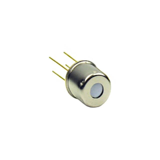
The TSD Series are digital thermopile sensors in a TO5 package. The
TSD sensors include an infrared sensor (thermopile) and a sensor
signal conditioner.
The TSD sensors can be interfaced to any microcontroller by an I2C
interface. This microcontroller has to calculate the temperature results
based on the ADC values and the calibration parameters
Features
0°C … up to +300°C
measurement ranges
Small size
Small field of view available
Up to ±1°C accuracy
I2C Interface
Low current consumption
Operating Temperature
Range: -10°C … +85°C
Applications
Contactless temperature
measurement
Climate control
Industrial process control
Household applications
CLICK HERE ›
CONNECT WITH A SPECIALIST
TE CONNECTIVITY SENSORS /// DATASHEET TSD305 SERIES
10/2021
Page 1
�TSD305 SERIES
Digital Thermopile Sensor
Absolute Maximum Ratings
Absolute maximum ratings are limiting values of permitted operation and should never be exceeded under the worst possible
conditions either initially or consequently. If exceeded by even the smallest amount, instantaneous catastrophic failure can
occur. Even if the device continues to operate satisfactorily, its life may be considerably shortened.
Parameter
Symbol
Condition
Min
Typ
Max
Unit
Supply voltage
VDD
---
-0.3
---
+3.63
V
Storage temperature
Tstor
dry
-20
---
+85
°C
VDD VIO
---
-0.5
---
VDD +0.5
V
IIN
---
-100
---
100
mA
ESD rating
ESD
Human Body Model
-2
---
+2
kV
Humidity
Hum
---
Voltage at supply and IO pins
Current into supply and IO pins
Non condensing
---
Operating Conditions
If not otherwise noted, 3.3V supply voltage is applied.
Parameter
Symbol
Condition
Min
Typ
Max
Unit
Operating supply voltage
VDD
stabilized, 100nF
1.68
---
3.6
V
VDD rise time
tVDD
---
---
---
200
µs
Operating temperature
Top
---
-20
---
+85
°C
Resolution
RES
---
---
---
0.1
°C
Supply Current
IVDD
Active state, average
---
1050
1500
µA
Sleep state, idle current
---
20
25
nA
Serial data clock I2C
FSCL
---
10
100
400
kHz
Self-heating
SH
1 sample/s, still air, 60s
---
---
+0.2
°C
CVDD
Place close to the sensor
---
100
---
nF
Min
Typ
Max
VDD capacitor
Thermopile Component
If not otherwise noted, 3.3V supply voltage is applied.
Parameter
Absorber area
Symbol
Condition
Sensor
A
---
---
At 50% of maximum signal
Field of view
Filter transmission range
FOV
---
0.8 x 0.8
Unit
mm
TSD305-1C55
TSD305-2C55
TSD305-3C55
---
88
---
deg
TSD305-1SL10
---
10
---
deg
Long wave pass
TSD305-1C55
TSD305-2C55
TSD305-3C55
>5.5
µm
Silicon lens, no coating
TSD305-1SL10
≥1.1
µm
TE CONNECTIVITY SENSORS /// DATASHEET TSD305 SERIES
10/2021
Page 2
�TSD305 SERIES
Digital Thermopile Sensor
Analogue to Digital Converter
Parameter
Symbol
Condition
Min
Typ
Max
Unit
Resolution
ADCRES
---
---
16
---
bit
tCONV
---
---
44.8
59.2
ms
t63
Including rise time of sensor element
---
---
44.8
ms
ITSRES
---
---
0.003
---
K/LSB
Symbol
Sensor
Min
Typ
Max
Unit
TSD305-1C55
TSD305-3C55
0
---
+100
°C
TSD305-2C55
TSD305-1SL10
0
---
+300
°C
Conversion time
Rise time
Resolution internal temperature
sensor
Object temperature range
Parameter
Object temperature range
1)
1)
TOBJ
Other temperatures on request
Tolerances
If not otherwise noted, 3.3V supply voltage is applied.
Parameter
Accuracy Standard Temp 1)
Symbol
Tsen = sensor temperature, Tobj = object temperature
Sensor Temperature
ACCS
+15°C < Tsen < +35°C
Sensor
Object Temperature
TSD305-1C55
TSD305-3C55
+40°C < Tobj < +80°C
TSD305-2C55
TSD305-1SL10
+170°C < Tobj < +190°
Complete range
Accuracy Extended Temp. 1 2)
TSD305-1C55
TSD305-3C55
+15°C < Tsen < +35°C
ACCE1
Complete range
TSD305-2C55
TSD305-1SL10
+15°C < Tsen < +35°C
Accuracy Extended Temp. 2 2)
ACCE3
Unit
±1
%FS
±2
%FS
±3
%FS
+40°C < Tobj < +80°C
Complete range
+170°C < Tobj < +190°
Complete range
TSD305-1C55
TSD305-2C55
TSD305-3C55
TSD305-1SL10
Complete range
Max
Complete range
Other temperature ranges and accuracies are available on request.
1) Ideal, proved by production
2) Ideal case by design
Power & Reset
Parameter
Symbol
Condition
Min
Typ
Max
Unit
tSTA1
VDD ramp up to interface
communication
---
---
1
ms
tSTA2
VDD ramp to first ADC measurement
---
---
2.5
ms
tWUP1
Sleep to active state interface
communication
---
---
0.5
ms
tWUP2
Sleep to first ADC measurement
---
---
2
ms
tRESET
VDDlow
3
---
---
µs
VDD low level
VDDlow
---
0
---
0.2
V
VDD rising slope
SRVDD
---
10
---
---
V/ms
Start-up time
Wake up time
Power down time for reset
TE CONNECTIVITY SENSORS /// DATASHEET TSD305 SERIES
10/2021
Page 3
�TSD305 SERIES
Digital Thermopile Sensor
Dimensions
If not specified, all tolerances according DIN ISO 2768-m.
TSD305-1C55
TSD305-2C55
TSD305-3C55
TSD305-1SL10
Pin Function Table
Pin
Name
Type
Function
1
SCL
DI
I2C Clock
2
SDA
DIO
I2C Data
3
VDD
P
Supply Voltage
4
VSS
P
Ground
I²C Interface
An I2C communication message starts with a start condition and it is ended by a stop condition.
Most commands consist of two bytes: the address byte and command byte.
I²C ADRESS
The standard I2C address is
Sensor
I2C Address Hex
I2C Address Bin
TSD305-1C55
TSD305-2C55
TSD305-1SL10
0x00
0b0000000X
TSD305-3C55
0x1E
0b0011110X
X = 0:
I2C Write
X = 1:
I2C Read
TE CONNECTIVITY SENSORS /// DATASHEET TSD305 SERIES
10/2021
Page 4
�TSD305 SERIES
Digital Thermopile Sensor
Status Byte
Each return starts with a status byte followed by the requested data word.
Bit
7
6
5
4
3
2
1
0
Meaning
---
---
Busy
---
---
Memory
Error
---
---
Busy:
1 = Sensor is busy. The requested data is not available yet.
Memory Error:
1 = Memory integrity check failed. Memory was changed after factory calibration.
COMMANDS
Note: Each return starts with a status byte followed by the requested data word. Please take care to wait a certain time after
write command before read data.
Command
Return
Description
Typical update rate
16 bit EEPROM data
Read data from EEPROM address (0x00 …
0x39) matching the command
---
0xAF
24 bit object temperature ADC,
24 bit sensor temperature ADC
Measure object temperature and sensor
temperature ADC 16 times and calculates
mean value. Store data in output buffer.
45 ms
0xAE
24 bit object temperature ADC,
24 bit sensor temperature ADC
Measure object temperature and sensor
temperature ADC 8 times and calculates
mean value. Store data in output buffer.
20 ms
0xAD
24 bit object temperature ADC,
24 bit sensor temperature ADC
Measure object temperature and sensor
temperature ADC 4 times and calculates
mean value. Store data in output buffer.
15 ms
0xAC
24 bit object temperature ADC,
24 bit sensor temperature ADC
Measure object temperature and sensor
temperature ADC 2 times and calculates
mean value. Store data in output buffer.
10 ms
0xAA
24 bit object temperature ADC,
24 bit sensor temperature ADC
Measure object temperature and sensor
temperature ADC 1 times and calculates
mean value. Store data in output buffer.
5 ms
0x00 … 0x39
Best signal to noise ratio will be achieved using command “0xAF” since this uses the maximum oversampling rate of 16
measurements.
TE CONNECTIVITY SENSORS /// DATASHEET TSD305 SERIES
10/2021
Page 5
�TSD305 SERIES
Digital Thermopile Sensor
Read EEPROM
Write Command:
Read EEPROM Data:
Perform Measurement and Read ADC Data
Write Command:
Read ADC Data:
TE CONNECTIVITY SENSORS /// DATASHEET TSD305 SERIES
10/2021
Page 6
�TSD305 SERIES
Digital Thermopile Sensor
EEPROM Content
Address / hex
Address / dec
Description
Name
Format
0x00
0x01
0
1
-----
0X02
2
Lot Nr.
Serial Number
I2C Address
0x03 ... 0x19
0x1A
0x1B
0x1C
0x1D
0x1E
0x1F
0x20
0x21
0x22
0x23
0x24
0x25
0x26
0x27
0x28
0x29
0x2A
0x2B
0x2C
0x2D
0x2E
0x2F
0x30
0x31
0x32
0x33
0x34
0x35
0x36
0x37
2 ... 25
26
27
28
29
30
31
32
33
34
35
36
37
38
39
40
41
42
43
44
45
46
47
48
49
50
51
52
53
54
55
Valid range: 0x00 … 0x7F,
0x04 … 0x07 are reserved
0x38
56
Example
Content
Value
UINT16
UINT16
15001
12345
YY WWW
Number
I2CAdd
UINT16
0x00
0
Factory Calibration Data
Min. Sensor Temp. / °C
Max. Sensor Temp. / °C
Min. Object Temp. / °C
Max. Object Temp. / °C
--TSenMin
TSenMax
TObjMin
TObjMax
TC
Reference Temperature
TREF
--0xFFEC
0x0055
0x0000
0x0064
0xBB96
0xBB99
0x41D7
0x70A4
0x3A07
0x4C8C
0x3F10
0x5CEC
0x4367
0x0D1F
0x4724
0x5A6F
0xC9A0
0x254D
----0x944B
0xD24F
0x2052
0xF1C2
0xABE5
0x991B
0x3797
0x2BBF
0x41D7
0x6DBA
---20°C
+85°C
0°C
100°C
Temperature Coefficient
--SINT16
SINT16
SINT16
SINT16
IEEE 754 H-Word
IEEE 754 L-Word
IEEE 754 H-Word
IEEE 754 L-Word
IEEE 754 H-Word
IEEE 754 L-Word
IEEE 754 H-Word
IEEE 754 L-Word
IEEE 754 H-Word
IEEE 754 L-Word
IEEE 754 H-Word
IEEE 754 L-Word
IEEE 754 H-Word
IEEE 754 L-Word
----IEEE 754 H-Word
IEEE 754 L-Word
IEEE 754 H-Word
IEEE 754 L-Word
IEEE 754 H-Word
IEEE 754 L-Word
IEEE 754 H-Word
IEEE 754 L-Word
IEEE 754 H-Word
IEEE 754 L-Word
UINT16
TBD
Compensation
Coefficient k4
Compensation
Coefficient k3
Compensation
Coefficient k2
Compensation
Coefficient k1
Compensation
Coefficient k0
Not used
ADC T
Coefficient k4
ADC T
Coefficient k3
ADC T
Coefficient k2
ADC T
Coefficient k1
ADC T
Coefficient k0
Factory calibration status –
internal usage only
k4comp
k3comp
k2comp
k1comp
k0comp
--k4Obj
k3Obj
k2Obj
k1Obj
k0Obj
---
-0.0046
26.93
5.161E-04
5.639E-01
2.311E+02
4.207E+04
-1.312E+06
---1.029E-26
1.787E-19
-1.631E-12
1.802E-05
2.693E+01
---
Change of I²C Address
The I2C address of each TSD can be modified to use multiple TSDs on one I2C bus. The used I2C address is configured via an
EEPROM address. Power needs to be cycled to active an updated I 2C address.
Command
Return
Description
0x00 … 0x39
16 bit EEPROM data
Read data from EEPROM address (0x00 … 0x39) matching the
command
0x40 … 0x79
---
Write data from EEPROM address (0x00 … 0x39).
0x90
---
Calculate and write memory checksum (CRC).
If the CRC is valid, then the “Memory Error” status bit is set to 0.
TE CONNECTIVITY SENSORS /// DATASHEET TSD305 SERIES
10/2021
Page 7
�TSD305 SERIES
Digital Thermopile Sensor
The commands to read and write the EEPROM are shown below. After changing the I2C address, the checksum needs to be
recalculated to reset the Memory Error bit.
Number Format
UINT16
Description:
Unsigned integer
Bits
16
Min (dec/hec/bin)
0
Max (dec/hec/bin)
65,535 / 0xFFFF / 0b1111 1111 1111 1111
/ 0x0000 / 0b0000 0000 0000 0000
SINT16
Description:
Signed integer
Bits
16
Min (dec/hec/bin) -
32,768 / 0x8000 / 0b1000 0000 0000 0000
Max (dec/hec/bin)
32,767 / 0x7FFF / 0b0111 1111 1111 1111
FLOAT IEEE 754
Description:
Float
Bits
32
Min (dec/hec/bin)
-1.4E-45 / 0x80000001 / 0b1000 0000 0000 0000 0000 0000 0000 0001
Max (dec/hec/bin)
3.403E38 / 0x7f800000 / 0b0111 1111 1000 0000 0000 0000 0000 0000
Example:
H-Word 0x3DCC
L-Word 0xCCCD
0b0011 1101 1100 1100 1100 1100 1100 1101
0.1
FLOAT IEEE 754 Conversions
The two integer words can easily be converted to a floating-point number by using a union consisting of an
integer array and a float.
void main(void)
{
union
{
unsigned int iValue[2];
float fValue;
} MyUnion;
// 16bit unsigned integer
// float IEEE 754
while(1)
{
MyUnion.iValue[1] = 0x3dcc;
MyUnion.iValue[0] = 0xcccd;
//MyUnion.fValue = 0.1;
}
}
TE CONNECTIVITY SENSORS /// DATASHEET TSD305 SERIES
10/2021
Page 8
�TSD305 SERIES
Digital Thermopile Sensor
Temperature Calculation
Sensor Temperature
The sensor temperature TSen is calculated from the corresponding 24 bit ADC value ADCsen.
Name
Description
ADCsen
ADC Sensor Temperature
Format
Range
INT24
Min
Max
0
16,777,216
ADCsen is scaled to cover the complete sensor temperature range from TSenMin to TSenMax.
Adress / hex
Adress / dec
Description
Name
Format
Example
Value
Max
0x1A
26
Min. Sensor Temp. / °C
TSenMin
SINT16
0xFFEC
-20°C
0x1B
27
Max. Sensor Temp. / °C
TSenMax
SINT16
0x0055
+85°C
Formula:
Tsen = ADCsen / 224 (TSenMax - TSenMin) + TSenMin
Example:
ADCsen = 6,364,157
Tsen = 6,364,157 / 224 [+85°C – (-20°C)] + (-20°C) = 19.83°C
TE CONNECTIVITY SENSORS /// DATASHEET TSD305 SERIES
10/2021
Page 9
�TSD305 SERIES
Digital Thermopile Sensor
Object Temperature
The object temperature Tobj is calculated in dependence of the sensor temperature Tsen and ADCObj.
ADCobj is shifted by 223 in order to provide unsigned integer values for positive and negative measurement values.
Name
Description
ADC Object Temperature
Shifted by 223 (0 is represented by 8,388,608)
ADCobj
Range
Format
INT24
Min
Max
0
16,777,216
The process consists of three successive steps.
TC Correction Factor
Adress / hex
Adress / dec
0x1E
30
0x1F
31
0x20
32
0x21
33
Description
Name
Temperature Coefficient
TC
Reference Temperature
TREF
Formula:
TCF =
Example
Format
Content
IEEE 754 H-Word
0xBB96
IEEE 754 L-Word
0xBB99
IEEE 754 H-Word
0x41D7
IEEE 754 L-Word
0x70A4
Value
-0.0046
+26.93
Example:
1 + [(Tsen – Tref) TC]
Tsen =
+19.83°C
Tref =
+26.93°C
TC =
-0.0046
TCF =
1 + [(19.83 – 26.93) -0.0046]
= 1.0327
TE CONNECTIVITY SENSORS /// DATASHEET TSD305 SERIES
10/2021
Page 10
�TSD305 SERIES
Digital Thermopile Sensor
Temperature Compensation
Adress / hex
Adress / dec
0x22
34
0x23
35
0x24
36
0x25
37
0x26
38
0x27
39
0x28
40
0x29
41
0x2A
0x2B
Description
Name
Compensation
Coefficient k4
k4comp
Compensation
Coefficient k3
k3comp
Compensation
Coefficient k2
k2comp
Compensation
Coefficient k1
k1comp
Compensation
Coefficient k0
k0comp
Formula:
Offset =
Format
Example
Content
IEEE 754 H-Word
0x3A07
IEEE 754 L-Word
0x4C8C
IEEE 754 H-Word
0x3F10
IEEE 754 L-Word
0x5CEC
IEEE 754 H-Word
0x4367
IEEE 754 L-Word
0x0D1F
IEEE 754 H-Word
0x4724
IEEE 754 L-Word
0x5A6F
IEEE 754 H-Word
0xC9A0
IEEE 754 L-Word
0x254D
Value
5.161E-04
5.639E-01
2.311E+02
4.207E+04
-1.312E+06
Example:
k4comp Tsen4
+ k3comp Tsen3
+ k2comp Tsen2
+ k1comp Tsen
+ k0comp
Tsen =
+19.83°C
k4comp ... k0comp
See table above
Offset =
= 5.161·10-4 19.834
+ 5.639·10-1 19.833
+ 2.311·102 19.832
+ 4.207·104 19.83
+ -1.312·106
= -382,399
OffsetTC=
Offset TCF
OffsetTC =
= -382,399 1.0327
= -394,904
TE CONNECTIVITY SENSORS /// DATASHEET TSD305 SERIES
10/2021
Page 11
�TSD305 SERIES
Digital Thermopile Sensor
Object Temperature Determination
Adress / hex
Adress / dec
Description
Name
0x2E
46
0x2F
47
ADC T
Coefficient k4
k4Obj
0x30
48
0x31
49
ADC T
Coefficient k3
k3Obj
0x32
50
0x33
51
ADC T
Coefficient k2
k2Obj
0x34
52
0x35
53
ADC T
Coefficient k1
k1Obj
0x36
54
0x37
55
ADC T
Coefficient k0
k0Obj
Formula:
ADCComp =
Format
Example
Content
IEEE 754 H-Word
0x944B
IEEE 754 L-Word
0xD24F
IEEE 754 H-Word
0x2052
IEEE 754 L-Word
0xF1C2
IEEE 754 H-Word
0xABE5
IEEE 754 L-Word
0x991B
IEEE 754 H-Word
0x3797
IEEE 754 L-Word
0x2BBF
IEEE 754 H-Word
0x41D7
IEEE 754 L-Word
0x6DBA
Value
-1.029E-26
1.787E-19
-1.631E-12
1.802E-05
2.693E+01
Example:
OffsetTC + (ADCObj - 223)1
ADCObj =
10,738,758
k4Obj ... k0Obj
See table above
ADCComp =
= -394,904 + 10,738,758 – 8,388,608
= 1,955,246
ADCCompTC =
ADCComp / TCF
ADCCompTC =
= 1,955,246 / 1.0327
= 1,893,334
TObj =
k4Obj ADCCompTC4
+ k3Obj ADCCompTC3
+ k2Obj ADCCompTC2
+ k1Obj ADCCompTC
+ k0Obj
TObj =
= -1.029·10-26 1,893,3344
+ 1.787·10-19 1,893,3343
+ -1.631·10-12 1,893,3342
+ 1.802·10-5 1,893,334
+ 2.693·10
= 56.28°C
Valid if emissivity is 1 (100%). Otherwise the formula in brackets must be replaced by (ADCObj - 223) / See
chapter “Emissivity” on page 13 for details.
1
TE CONNECTIVITY SENSORS /// DATASHEET TSD305 SERIES
10/2021
Page 12
�TSD305 SERIES
Digital Thermopile Sensor
Example Code
This example code is meant to illustrate the basic procedure to determinate the measured sensor and object
temperatures with respect to TSD digital thermopile sensors. This code needs to be modified with respect to the
compiler used.
//******************************************************************************************//
// File: TSD_Temperature_Determination_Example.c //
// Date: 01.11.2016 //
// Description: This example code is meant to illustrate the basical procedure //
// to determinat the measured sensor and object temperatures with //
// respect to TSD digital thermopile sensors. //
// This code is not meant to work or to be compiled. //
//******************************************************************************************//
void TSD_Determinate_Temperature(void)
{
signed int siMinObjTemp, siMaxObjTemp, siMinSenTemp, siMaxSenTemp;
float fTC, fTref, fK4com, fK3com, fK2com, fK1com, fK0com, fK4obj, fK3obj,
fK2obj, fK1obj, fK0obj;
float fTsen, fTobj;
float fTCF, fOffset, fADCcomp;
signed long slADC_Object, slADC_Sensor;
// Read Temperature Range Minimum & Maximum
siMinSenTemp = (signed int)Read_EE_UInt(26);
siMaxSenTemp = (signed int)Read_EE_UInt(27);
siMinObjTemp = (signed int)Read_EE_UInt(28);
siMaxObjTemp = (signed int)Read_EE_UInt(29);
// Read all necessary coefficients from the memory, float tye
fTref = Read_EE_Float(32);
fTC = Read_EE_Float(30);
fTref = Read_EE_Float(32);
fK4com = Read_EE_Float(34);
fK3com = Read_EE_Float(36);
fK2com = Read_EE_Float(38);
fK1com = Read_EE_Float(40);
fK0com = Read_EE_Float(42);
fK4obj = Read_EE_Float(46);
fK3obj = Read_EE_Float(48);
fK2obj = Read_EE_Float(50);
fK1obj = Read_EE_Float(52);
fK0obj = Read_EE_Float(54);
// Read ADC Values for Object Temp. & Sensor Temp.
Read_ADC_Values(&slADC_Object, &slADC_Sensor);
// Calculate Sensor Temp. (slADC_Sensor, Minimum & Maximum Sensor Temp.), Page 8
fTsen = (float)slADC_Sensor / 16777216.0 * (siMaxSenTemp - siMinSenTemp) + siMinSenTemp;
// Calculate TC Correction Factor (Temp. Coefficient & Reference Temp.), Page 9fTCF = 1.0
+ ((fTsen - fTref) * fTC);
// Calculate Offset
fOffset = fOffset +
fOffset = fOffset +
fOffset = fOffset +
fOffset = fOffset +
fOffset = fOffset +
fOffset = fOffset *
Value, Page 10
fK4com * fTsen * fTsen * fTsen * fTsen;
fK3com * fTsen * fTsen * fTsen;
fK2com * fTsen * fTsen;
fK1com * fTsen;
fK0com;
fTCF;
// Align ADC Value for Object Temperature, Page 11
slADC_Object = slADC_Object - 8388608;
}
// Calculate Object Temperature, Page 11
fADCcomp = (float)slADC_Object + fOffset;
fADCcomp = fADCcomp / fTCF;
fTobj = fTobj + fK4obj * fADCcomp * fADCcomp * fADCcomp * fADCcomp;
fTobj = fTobj + fK3obj * fADCcomp * fADCcomp * fADCcomp;
fTobj = fTobj + fK2obj * fADCcomp * fADCcomp;
fTobj = fTobj + fK1obj * fADCcomp;
fTobj = fTobj + fK0obj;
// Resulting Sensor Temperature = fTsen
// Resulting Object Temperature = fTobj
TE CONNECTIVITY SENSORS /// DATASHEET TSD305 SERIES
10/2021
Page 13
�TSD305 SERIES
Digital Thermopile Sensor
Application notes
field of view
The thermopile’s field of view must be directed to the object surface of interest. The distance to the surface or the
surface diameter must be adjusted to ensure that the complete sensors field of view is covered by the object, see
example on the left in the picture below.
TSD3051C55
TSD3052C55
TSD3051SL10
TE CONNECTIVITY SENSORS /// DATASHEET TSD305 SERIES
Distance
/ mm
Min. Diameter
/ mm
10
24
20
43
30
62
40
82
50
101
100
198
200
391
300
584
400
777
500
970
Distance
/ mm
Min. Diameter
/ mm
10
6
20
8
30
10
40
11
50
13
100
22
200
39
300
57
400
74
500
92
10/2021
Page 14
�TSD305 SERIES
Digital Thermopile Sensor
Direct Sunlight
Sun light radiation which is transmitted through a glass window may influence the measurement accuracy. To avoid
this, the thermopile sensor is equipped with a long wavelength filter. Due to not ideal filter characteristics a small
portion of radiation will be added to the radiation of the object. In case of direct sunlight exposure this error can be up
to +0.2°C.
Touching the Sensors Cap
User should avoid touching the sensors cap. There will still be a measurement deviation after changing the sensors
temperature rapidly.
Emissivity
Every object is transmitting infrared energy in dependence to its temperature. The emissivity is the ratio of the
radiated power by an object to the radiation of an ideal black body. Common materials like liquids, clothes, human
skin, foods have emissivity factors >0.90 and therefore they can be measured very accurately without adopting the
sensors specification.
To compensate the measurement for an object with significant low emissivity, ADCobj needs to be adjusted.
Name
Description
ADCobj
ADC Object Temperature
Shifted by 223 (0 is represented by 8,388,608)
Emissivity
Formula:
Min
Max
INT24
0
16,777,216
100%
0
1
Example:
ADCObj =
10,738,758
=
ADCCorr =
Range
Format
(ADCObj - 223) /
Material
Emissivity
0.9 (90%)
ADCCorr =
= 2,611,278
Material
Aluminum
Emissivity
Human Skin
0.99
Polished
0.10 – 0.05
Oxidized
0.10 – 0.40
Polished
0.20
Rough
0.10 – 0.30
Oxidized
0.50 - 0.95
Anodized
0.60 – 0.95
Rusted
Asphalt
Iron
0.50 – 0.70
0.90 – 1.00
Paint
Brass
Aluminum paint
Polished
0.05
Oxidized
0.50 - 0.60
Burnished
0.30
Ceramic
0.90 – 0.95
Copper
0.60 – 0.90
On plastic, wood
0.80 – 0.95
Paper
0.85 – 1.00
Plastic
0.95 – 1.00
0.10
Oxidized
0.20 – 0.80
Polished
0.85 – 1.00
Oxidized
Gold
Stainless Steel
0.05
Glass
Plate
Fused quartz
0.90 – 0.95
0.75
TE CONNECTIVITY SENSORS /// DATASHEET TSD305 SERIES
0.80
On metal
Polished
Foods
0.50
Bronze paint
0.10 – 0.15
0.45 - 0.95
Water
Liquid
0.90 – 0.95
Ice
0.95 – 1.00
Snow
0.80 – 1.00
10/2021
Page 15
�TSD305 SERIES
Digital Thermopile Sensor
Evaluation Kit
General description
For easy usage and first trials an evaluation kit is available. It consists of an evaluation board and the “DTS-Viewer”-Software.
The eval-board provides an USB to I²C interface and can be used on Windows PCs and Android Smartphones with an OTG
capable USB port. That means that for example USB flash drives can be connected by an OTG cable to the phone.
The “DTS-Viewer”-Software enables easy measurements and datalogging. This software is available for Windows and Android
and supports a wide range of digital temperature sensors provided by TE.
Evaluation Board Hardware description
The following pictures are showing the top and the bottom side of the eval board PCBA.
It is equipped with the Microchip™ MPC2221 USB to I²C transceiver, a voltage regulator and some passive components. A
status LED (red circle) on the bottom of the PCBA indicates power supply and data transmission.
The TSD must be plugged into the white TO socket; the indicator flag of the TSD has to be matched with notch at the socket.
The connection to the PC has to be done by a USB cable with Mini-USB-B-plug on the module’s side. For connecting to a
smartphone an OTG cable is required. This type of cable is used to connect a slave USB device to the USB connector of the
smartphone.
LED Function Table
On state
Function
On
Power on
Flashing
Access / data transmission
DTS-Viewer description (PC version V1.X)
Overview
The software read out suitable temperature sensors that communicate with an MCP2221 via USB.
The software can display the temperatures measured by the respective sensor and at the same time display the time course of
the last 50 measured values in a graph.
In addition, the measured temperatures can be recorded in a text file via the logging function.
During the measurement it is possible to put a filter over the measured values and to vary the measuring speed in given
intervals.
To use the software no special installation process is required. Just start the executable file on the USB flash drive that is
provided with the evaluation kit.
The following picture shows the main window that appears after starting the executable file.
TE CONNECTIVITY SENSORS /// DATASHEET TSD305 SERIES
10/2021
Page 16
�TSD305 SERIES
Digital Thermopile Sensor
Measurement
First, the evaluation board equipped with a TSD must be connected to the PC.
By pressing the START-button the measurement of both temperatures, sensor package and object temperature is started.
Pressing the STOP-button stops the measurement. Disconnecting the sensor board from the PC has the same effect.
Please note that the DTSViewer V1.X only uses the command “0xAF” with 16 times oversampling. To perform faster
measurements the Beta-version of DTSViewer V2.X must be used. See Chapter “Changes in DTSViewer V2.X beta”
for details.
Switching the temperature Unit
The temperature unit can be changed only when the measurement is running. This is done by clicking on the “Measurement
Unit”-Symbol on the lower left area. °C and °F can be selected.
Measurement Speed
In the drop-down menu "Measurements/s" the measurement speed can be selected, both before and during a running
measurement.
You can select from a predefined selection of measurement speeds. The minimum measurement interval is limited by the
internal measurement speed of the sensor.
TE CONNECTIVITY SENSORS /// DATASHEET TSD305 SERIES
10/2021
Page 17
�TSD305 SERIES
Digital Thermopile Sensor
Filter
The "Filter" button enables or disables a filter to smooth the measured values. It can be pressed before or during
measurement.
The filter used is a very simple implementation of a moving average filter, which is only intended to provide smoothing for
unstable measured values. In this implementation the filter considers the last 5 measured values.
Note: If the measured values must be as accurate as possible or if a fast reaction time is required, the filter should be switched
off.
Logging
The software can record the measurement data in a text file. The "Enable Logging" button toggles between recording on and
off.
If the logging is set to "ON" the user is prompted to select or create a text file which is then used to save the measurement
data each time he starts the measurement.
The text file begins with the time and date information and a description of the format used. Then follows the listing of the
measured values, together with sensor type and an individual time stamp.
It should be noted that the measured values are always stored in °C and unfiltered, regardless of what the user has previously
set in the program. Only the measuring speed has an influence on the stored data.
Note: The measurement data are stored as tabulator delimited values, so each value is written into a new cell if the measured
values are copied into an Excel worksheet.
Configuring a new Sensorboard – internal usage only
To use this function, the user must right-click on the "START" button and then click on the button that appears.
This function is for internal usage only and could lead to malfunction of the evaluation board. If the user activates the function
by accident he should leave everything as it is and skip it.
TE CONNECTIVITY SENSORS /// DATASHEET TSD305 SERIES
10/2021
Page 18
�TSD305 SERIES
Digital Thermopile Sensor
Changes in DTSViewer V2.X beta
Overview
The following changes taken place in the DTSViewer V2.X:
Main screen with slightly different menu bar at the bottom
Measurement speed adjustable by slider. Limitation of 20 measurements per second can be overridden to achieve faster
measurement with lower oversampling.
New advanced menu to
o
Configure TSD oversampling rate “TSD Speed” by using different commands – will be reset to 16 measurements after
program restart
o
Configure TSD I²C address and set the software to different I²C address than 0x00.
o
Configure the eval boards for different TE digital sensors – internal usage only.
Currently, there is no possibility to measure the temperatures in °F. This will maybe back in the official released version.
Main Screen
The main screen of DTSViewer V2.X looks like follows
Measurement speed
The following pictures show the new design of the measurement/s menu. The left picture shows the slider. When enabling faster speeds by
clicking the checkbox the right menu appears.
Since this is only the request frequency of the display and logging but not the sensor update rate the user has to take care to set the sensor
speed accordingly. See “TSD Speed Config” below. Otherwise the program could crash.
TE CONNECTIVITY SENSORS /// DATASHEET TSD305 SERIES
10/2021
Page 19
�TSD305 SERIES
Digital Thermopile Sensor
Advanced Menu
By clicking the “Advanced” button the following menu appears:
Change TSD Speed
The “Change TSD Speed” menu enables the user to temporary change the oversampling rate of the sensor. As mentioned in the datasheet
there are 5 different commands initiate a measurement cycle at the TSD. Per default the command “0xAF” is used where 16 measurements
are taken and are internally processed to an average value. To accelerate sensor data output this oversampling rate can be modified using a
different measurement command. The pictures below show the process how to change the measurement command used by the software.
This will not be stored in a config file therefore the setting after program start is always “0xAF”.
By clicking “Get current Setting” the current command the software uses is read. In the pull-down menu the user can now change the
command to the one he would like to use. By clicking “Set new Measurement Speed” the value is taken and the software will use the new
command now.
Change TSD Address
To change the I²C address of the TSD the user must search for a TSD first by clicking “Search for TSD”. Then the I²C bus is scanned for a
TSD. If one is found the software shows the address at “Current address”. IN the field “New address” the new address can be selected. “Set
new Address” writes the value to the TSDs EEPROM. Then a message appears to perform one power cycle to make the change active.
Per default DTSViewer uses I²C address 0x00. If there is no TSD with this address a message appears if the user wants to scan the bus. By
clicking “Yes” the bus is scanned and the Software uses now the I²C address of the connected sensor.
TE CONNECTIVITY SENSORS /// DATASHEET TSD305 SERIES
10/2021
Page 20
�TSD305 SERIES
Digital Thermopile Sensor
Sensorboard Config
This function is for internal usage only.
TE CONNECTIVITY SENSORS /// DATASHEET TSD305 SERIES
10/2021
Page 21
�TSD305 SERIES
Digital Thermopile Sensor
Order Information
Further customer specific adaptations are available on request. Please refer to the table below for part name, description and
order information.
Part Number
Part Desription
Comment
G-TPMO-101
TSD305-1C55 Digital Thermopile Sensor
TO5, I2C Interface, 0°C … +100°C
10205977-00
TSD305-2C55 Digital Thermopile Sensor
TO5, I2C Interface, 0°C … +300°C
10207697-00
TSD305-3C55 Digital Thermopile Sensor
TO5, I2C Interface Add=0x1E, 0°C … +100°C
10213286-00
TSD305-1SL10 Digital Thermopile Sensor
TO5, FOV=10°, I2C Interface, 0°C … +300°C
20006766-00
TSD305-Series Evaluation Kit
Contains evaluation board, one piece G-TPMO-101
and 104 and the DTS-Viewer software on USB drive
EMC
Due to the use of these modules for OEM application no CE declaration is done. Especially line coupled disturbances like
surge, burst, HF etc. cannot be removed by the module due to the small board area and low-price feature. There is no
protection circuit against reverse polarity or over voltage implemented. The module will be designed using capacitors for
blocking and ground plane areas in order to prevent wireless coupled disturbances as good as possible.
CLICK HERE ›
CONNECT WITH A SPECIALIST
NORTH AMERICA
Tel +1 800 522 6752
EUROPE
Tel +31 73 624 6999
ASIA
Tel +86 0400 820 6015
te.com/sensors
TE Connectivity, TE, TE Connectivity (logo) and Every Connection Counts are trademarks. All other logos, products and/or company names referred to herein might
be trademarks of their respective owners
The information given herein, including drawings, illustrations and schematics which are intended for illustration purposes only, is believed to be reliable. However,
TE Connectivity makes no warranties as to its accuracy or completeness and disclaims any liability in connection with its use. TE Connectivity‘s obligations shall
only be as set forth in TE Connectivity‘s Standard Terms and Conditions of Sale for this product and in no case will TE Connectivity be liable for any incidental,
indirect or consequential damages arising out of the sale, resale, use or misuse of the product. Users of TE Connectivity products should make their own evaluation
to determine the suitability of each such product for the specific application.
© 2021 TE Connectivity Corporation. All Rights Reserved.
Version 2 05/2021
TE CONNECTIVITY SENSORS /// DATASHEET TSD305 SERIES
10/2021
Page 22
�