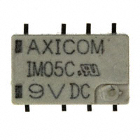
Signal Relays
AXICOM
IM Relay
line 10x6mm, low profile 5.65mm and min. board-space 60mm2
n Switching current 2/5A, switching power 60W/62.5VA and
switching voltage 220VDC/250VAC
n Low coil power consumption,
140mW standard, 100mW for high sensitive version, 50mW for ultra
high sensitive version and 100mW for bistable version
n High dielectric and surge capability up to 2500Vrms between open
contacts and 2500Vrms between coil and contacts
n High mechanical shock resistance up to 50g functional
n Slim
Typical applications
Telecommunication, access and transmission equipment, optical network
terminals, modems, office and business equipment, consumer electronics,
AXICOMÊSignalÊRelays
measurement and test equipment, industrial
control, medical equipment,
IM Relay
HVAC
U
108-98001 Rev. M
Approvals
Contact Data
Contact Data (continued)
UL 508 File No. E 111441
Electrical endurance
at contact
application
0
IM-D
IM-E
(≤30mV/≤10mA)
min. 2.5x10⁶ operations
Number of contacts and type
1ÊPoleÊbreak
1ÊPoleÊmake
1ÊPoleÊÊ
2ÊPoleÊbreak
2ÊPoleÊmake
Contact Data
standard, C D, I
P
cable load open end
min. 2.0x10⁶ operations
changeover
Contact assembly
BifurcatedÊcontacts
standard and
high
high contact
resistive, 125VDC / 0.24A - 30W
min. 5x10⁵ operations
Contact material
Palladium-ruthenium,Êgold-covered
high dielectric current
stability
resistive, 220 VDC / 0.27A - 60W
min. 1x10⁵ operations
Limiting continuous current
2ÊA
2ÊA
4ÊA resistive,
2ÊA250VAC / 2ÊA
version
version
version
0.25A - 62.5VA
min. 1x10⁵ operations
at max. ambient temperature
Contact arrangement
2 form C, 2 CO
resistive, 30VDC / 1A - 30W
min. 5x10⁵ operations
Maximum switching current
2ÊA
2ÊA
3ÊA
2ÊA
2ÊA
Max. switching
voltage
220VDC,
220VDC,
220VDC,
resistive,
30VDC
/
2A
60W
min. 1x10⁵ operations
Maximum
swichting voltage
220ÊVdc
250VAC 250VAC 250VAC
UL contact rating 30VDC, 2A, 60W, NO only
250ÊVac
Maximum switching capacity
Rated current
2A
5A
2A
110VDC, 0.3A, 33W
60ÊW,Ê62.5ÊVA
Thermoelectric
potential
Limiting continuous
current
2A
5A
2A
220VDC, 0.27A, 60W
10
Version
Narrow
Version
IM
Relay 405
23
500
50
Capacitance
Coil5 Operating5.00
Range 0.50
26 12 12.00 1.20
2880 50
between open contacts
max. 1pF
All figures are given for coil without pre-energization, at ambient temperature +23°C
between contact and coil
max. 2pF
Coil Operating Range
Unom
Nominal
coil voltage
= between
adjacent
contacts
max.10.0±0.08
2p
5.7±0.3
3.4
50mW coil
6.0±0.08
10.0±0.08
3.2 range, sensitive and ultra high sensitive
Coil operating
5.7±0.3
Umax.
=10.0±0.08
Upper limit of6.0±0.08
the operative range of
10.0±0.08
100mW coilcoil
=
Unom. nominal coil voltage
Umax. at 2x2A
Urel. min.
1
0.4
0.8
0.2
0.60
0.4 -50
-40
-30
-20
-10
0.2
0
10
20
30
40
50
60 70 80
Urel. min.
90
10 0 1 10 12 0
Ambient Temperature [°C]
0
-50
-40
-30
-20
-10
0
10
20
30
40
50
60
70
80
90
10 0 1 10 12 0
Ambient Temperature [°C]
0.3±0.05
2.2±0.15
2.2±0.15
3.2±0.15
2.2±0.15
2.2±0.15
2.2±0.15
2.2±0.15
3.2±0.15
3.2
3.2
5.8±0.08
0.75
3.2
Voltage
standing wave
(VSWR)
Mounting
Holeratio
Layout
at 100MHz/900MHz
Mounting
Hole Layout
0.4
0.4
3.2±0.15
Urel. min.
rel. min.
UopUmin.
2.2±0.15
Uop min.
Unom. nominal coil voltage
2.2±0.15
1.4
0.8
1.2
0.6
Lower
limit ofrelays
the 0.4
operative
For latching
Uset min.range
resp.of
the
coil0.4
voltage (reliable operate voltage)
Ureset
min.
5.08±0.1
For
latching
relays
Uset min.range
resp. of
=
Lower
limit of
the operative
5.08±0.1
RF Data
Ureset
the coilmin.
voltage (reliable release voltage)
Isolation
at 100MHz/900MHz
=
Lower
limit of the operative range of
Insertion
lossvoltage
at 100MHz/900MHz
the coil
(reliable release voltage)
3.2±0.15
2
1.4
1.8
1.2
1.61
Umax. at 0A
3.2
Coil Voltage
Coil [U/Unom]
Voltage [U/Unom]
2.4
1.8
2.2
1.6
5.8±0.08
Uop. min.
Umax. at 0A
Umax. at 2x1A
0.75
Umax. at 0A
Umax. at 2x2A
3
2.4
2.8
2.2
2.62
50mW
Umax.coil
at 0A
100mW coil
5.65-0.2
*this
(Sulfur hexafluoride, CAS number: 2551-62-4) for dielectric strength
= relay
Nominal
coilSF6
voltage
thecontains
coil voltage
(limiting voltage) when
enhancement, SF6 is hermetically sealed in relay without leaks to air during normal applicacoils are
continously
energized
=
Upper
limit
of
the
operative
range
of specification. It is clarified that the usage
tion as recommended per the
applicable
product
coilsignal
voltage
(limiting
voltage)
when
= SF6the
Lower
limit
of
the
range
of
of
in mini
relay
isoperative
not prohibited
by
related regulations. Please contact TE local
coils
are
continously
energized
the
coil
voltage
operate voltage)
sales or
field
engineer
for(reliable
further
information
and detailed material declaration.
Umax. at 2x1A
5.65-0.2
Unom
Umax.
Uop. min.
3
3.4
2.8
3.2
2.6
SMT
Gull W
10.
0.3±0.05
THT Version
THT Version
0.4
3.2±0.1
3.2±0.15
Coil Data (continued)
3.2±0.1
37.0dB/18.8dB
0.03dB/0.33dB
Copla
1.06/1.49
Solder
View onto the component side of the PCB (top view)
View onto the component side of the PCB (top view)
Other Data
View o
W
Coil Voltage
[U/Unom[U/U
]
Coil Voltage
nom]
Material
compliance:
EU RoHS/ELV, China RoHS,
REACH,
Halogen content
3.4
Narrow
Version
Standard
Version
140mW coil
Coil versions,3.2 standard, bistable 1 coil
Version
refer to the Product
NarrowCompliance
Version Support Center at Gull
Standard
3
200mW coil
Coil
Rated
Set
Reset
Coil
Rated coil
www.te.com/customersupport/rohssupportcenter
3.4
2.8
Umax. at 2x1A
3.2
140mW
coil
2.6
code voltage voltage voltage
resistance
power
Ambient temperature
-40°C to +85°C
3
2.4
200mW coil
Umax. at 0A
VDC VDC VDC
Ω±10%
mW
Thermal
resistance
很抱歉,暂时无法提供与“IM05CGR”相匹配的价格&库存,您可以联系我们找货
免费人工找货