General Purpose Relays
PCB Relays
SCHRACK
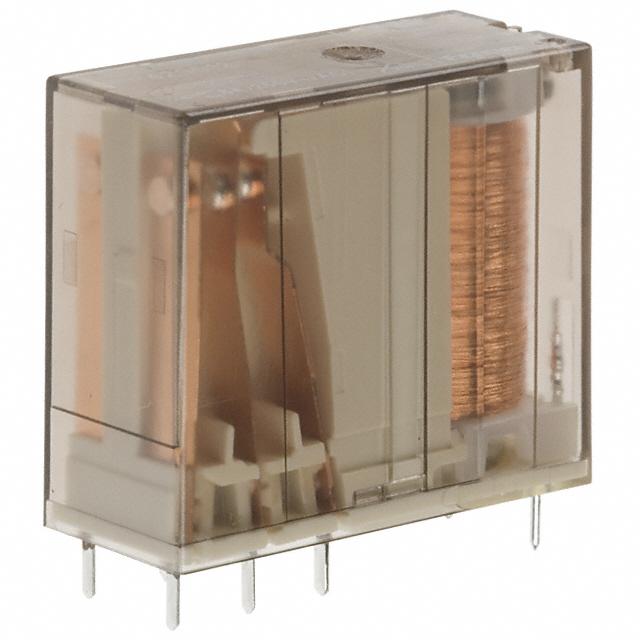
Power PCB Relay RPII/2
n 2
n 4
pole 8 A, 2 form C (CO) or 2 form A (NO) contacts
kv/8 mm coil contact
Applications
Domestic appliances, UPS
Z
Coil Data
Approvals
VDE Cert. No. 40025448, UL E214025
Coil voltage range
Operative range, IEC 61810
Technical data of approved types on request
Contact Data
F0150-B
5 to 110VDC
2
Contact configuration
2 form C (CO) or
2 form A (NO)
Rated voltage / max.switching voltage AC
250 VAC
Max. switching voltage
400 VAC
Rated current
8 A (UL: 10A)
Limiting making capacity, max 4 s, duty factor 10%
14 A
Breaking capacity max.
2000 VA
Contact material
AgNi 90/10
AgNi0.15 gold flashed
Frequency of operation with / without load
600 / 36000 h-1
Operate/release time typ.
9/3 ms
Bounce time typ., form A/form B
2/3 ms
Coil versions, DC coil
Coil
Rated
Operate
Release
Coil
Rated coil
code voltage voltage voltage
resistance power
VDC VDC VDC
Ω±10%1) mW
005 5 3.5 0.5 54 500
006 6 4.2 0.6 68 500
012 12 8.4 1.2 270 500
024
24
16.8
2.4
11001) 500
048
48
33.6
4.8
44001) 500
060
60
42.0
6.0
65401) 500
110 110 77.0 11.0
231001) 500
Contact ratings
Type
Contact Load
IEC61810
RP421
A (NO)
8A, 250 VAC, resistive, 35°C
RP424 DC-coil A (NO)
8A, 250 VAC, resistive, 35°C
RP424 DC-coil C (CO)
5A, 250 VAC, resistive, 70°C
RP424 DC-coil A (NO)
8A, 250 VAC, resistive, 70°C
RP424 REM
A (NO)
8A, 250 VAC, resistive, 35°C
UL508
RP421
C (CO)
8A, 250 VAC, gen. purp, 40°C
RP424
A (NO)
10A, 250 VAC, gen. purp, 65°C
RP424
C (CO)
8A, 250 VAC, gen. purp, 70°C
RP424
A (NO)
1/2 HP, 240 VAC, 70°C
Other coil voltages on request.
1) Coil resistance ±15%.
All figures are given for coil without pre-energization, at ambient temperature +20°C.
Cycles
100x103
100x103
20x103
30x103
50x103
6x10³
30x103
6x10³
6x10³
Coil versions, REM I (1 coil bistable/remanence)
Coil Rated Resistance Magnetisation range Demagnetisation range
code voltage Ω±15%
MIN./ Vdc MAX./Vdc MIN./ Vdc MAX./Vdc
VDC
A12
12
115
9
18
3
4.8
A24
24
460
18
36
6
9.6
A48
48
1748
36
72
12
19.2
Coil versions, REM II (2 coil bistable/remanence)
Coil Rated Resistance Magnetisation range Demagnetisation range
code voltage Ω±15%
MIN./ Vdc MAX./Vdc MIN./ Vdc MAX./Vdc
VDC
F05
5
20
3.7
7.5
3.7
6
F12
12
105
9
18
9
14.4
F24
24
460
18
36
18
28.8
All figures are given for coil without pre-energization, at ambient temperature +20°C.
Other coil voltages on request.
03-2019, Rev. 0319
www.te.com
© 2015 Tyco Electronics Corporation,
a TE Connectivity Ltd. company
Datasheets and product specification
according to IEC 61810-1 and to be used
only together with the ‘Definitions’ section.
Datasheets and product data is subject to the
terms of the disclaimer and all chapters of
the ‘Definitions’ section, available at
http://relays.te.com/definitions
Datasheets, product data, ‘Definitions’ section, application notes and all specifications
are subject to change.
1
�General Purpose Relays
PCB Relays
SCHRACK
Power PCB Relay RPII/2 (Continued)
Insulation
Initial dielectric strength
coil-contact circuit
open contact circuit
adjacent contact circuits
Clearance/creepage
coil-contact circuit
Material group of insulation parts
PCB layout / terminal assignment
4000Vrms
1000Vrms
2500Vrms
Bottom view on solder pins
Dimensions in mm
≥8/8mm
IIIa
Other Data
Material compliance: EU RoHS/ELV, China RoHS, REACH, Halogen content
refer to the Product Compliance Support Center at
www.te.com/customersupport/rohssupportcenter
Ambient temperature
-40 to +70°C
Category of environmental
IEC 61810 RTII - flux proof, RTIII - wash tight
Vibration resistance (functional),
form A/form B, 30 to 150Hz
11/1.5g
Shock resistance (destructive)
100g
Terminal type
PCB-THT
Resistance to soldering heat THT, IEC 60068-2-20
flux-proof version
270°C / 10s
wash-tight version
260°C / 5s
Relay weight
18g
Packaging unit tube/20 pcs., box/500 pcs.
S0163-CO
2 form C (CO) contacts
S0163-BJ
2 form A (NO) contacts
Dimensions
Dimensions in mm
S0163-BK
2 form C (CO) contacts (REM II version/ 2 coils)
a) Indicated contact
position while or after coil
energization with reset
voltage.
b) for 2 coil version only
S0273-AB
monostable and REM I (REM II version has 3 coil terminals)
Product code structure
Typical product code
RP
4
2
4
024
Type
RP Power PCB Relay RPII/2
Version
4 8A, flux proof
8
8A, wash tight
Contact arrangement
2 2 form C (2 CO)
4
2 form A (2 NO)
Contact material
1 AgNi0.15 gold flashed
0
Discontinued: AgCdO2)
Coil
4
AgNi 90/10
Coil code: please refer to coil versions table
2) AgCdO contacts are discontinued and replaced with AgNi contacts (see PCN E-18-003947)
2
03-2019, Rev. 0319
www.te.com
© 2015 Tyco Electronics Corporation,
a TE Connectivity Ltd. company
Datasheets and product specification
according to IEC 61810-1 and to be used
only together with the ‘Definitions’ section.
Datasheets and product data is subject to the
terms of the disclaimer and all chapters of
the ‘Definitions’ section, available at
http://relays.te.com/definitions
Datasheets, product data, ‘Definitions’ section, application notes and all specifications
are subject to change.
�General Purpose Relays
PCB Relays
SCHRACK
Power PCB Relay RPII/2 (Continued)
Product Code
Version
Contacts
Cont. Material
Coil Version
Coil
RP421012
RP421024
RP421110
RP821012
RP821024
RP424005
RP424006
RP424012
RP424024
RP424048
RP424060
RP424110
RP424A12
RP424A24
RP424A48
RP424F12
RP424F24
RP444012
RP444024
RP824006
RP824012
RP824024
RP824048
RP824060
RP844024
Flux proof
2 form C (CO) contacts
AgNi0.15
monostable
12VDC
24VDC
110VDC
12VDC
24VDC
5VDC
6VDC
12VDC
24VDC
48VDC
60VDC
110VDC
12VDC
24VDC
48VDC
12VDC
24VDC
12VDC
24VDC
6VDC
12VDC
24VDC
48VDC
60VDC
24VDC
Wash tight
AgNi0.15
Flux proof
AgNi 90/10
REM I
REM II
2 form A (NO) contacts
Wash tight
monostable
2 form C (CO) contacts
2 form A (NO) contacts
Part Number
6-1393234-7
6-1393234-8
7-1393234-1
1393845-4
1393845-5
6-1415546-2
6-1415546-3
6-1415546-4
6-1415546-5
6-1415546-6
6-1415546-7
6-1415546-8
6-1415546-9
7-1415546-0
7-1415546-1
7-1415546-2
7-1415546-3
7-1415546-4
7-1415546-5
7-1415546-6
7-1415546-7
7-1415546-8
7-1415546-9
8-1415546-0
6-1415546-1
Note. This list represents the most common types and does not show all variants covered by this datasheet. Other types on request.
03-2019, Rev. 0319
www.te.com
© 2015 Tyco Electronics Corporation,
a TE Connectivity Ltd. company
Datasheets and product specification
according to IEC 61810-1 and to be used
only together with the ‘Definitions’ section.
Datasheets and product data is subject to the
terms of the disclaimer and all chapters of
the ‘Definitions’ section, available at
http://relays.te.com/definitions
Datasheets, product data, ‘Definitions’ section, application notes and all specifications
are subject to change.
3
�