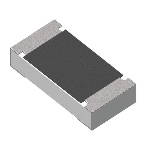
SMD Thin Film Precision Resistors - AEC-Q200 Compliant
Type RQ73 Series
Key Features
SMD TaN Thin
film resistor
Special
passivation
layer on
resistive
element
AEC-Q200
qualified
Sulfur resistant
(per ASTM
B809-95 humid
vapor test)
RoHS Compliant
TE Connectivity is proud to introduce this automotive grade thin film precision
chip resistor, a sister to our highly successful RN73 range. The resistors are
constructed in a high grade raw materials and laser trimmed to give precise
tolerance figures. This, coupled with the tight TCR and anti-corrosive protection
layer gives us a range of resistors which are ideal not just for automotive
applications, but also for medical equipment, measuring instruments and
industrial applications.
Characteristics – Electrical
Type
RQ73 1E
RQ73 1J
RQ73 2A
RQ73 2B
Size
0402
0603
0805
1206
Resistance tolerance
±0.1%
Resistance Range
40R ~ 35K
40R ~ 130K 10R ~ 350K 10R ~1M0
TCR (ppm/°C)
±10PPM/°C
Max. dissipation at
0.0625W
0.15W
0.2W
0.4W
Tamb=85°C
Max. Working Voltage
50V
75V
100V
200V
(DC or RMS)¹ ²
Max. Overload Voltage
100V
150V
200V
400V
(DC or RMS)
Operating Temperature
-55 ~ 155°C
Notes:
This is the maximum voltage that may be continuously supplied to the resistor
1.
element, see “IEC publication 60115-8”
2.
Max. Operation Voltage : So called RCWV (Rated Continuous Working Voltage) is
determined by
RCWV = √ Rated Power x Resistance Value or Max. RCWV listed above,
whichever is lower.
1773270-2 Rev A 06 / 2018
Dimensions in
millimetres unless
otherwise specified
Dimensions Shown for
reference purposes only.
Specifications subject to
change
For Email, phone or live chat,
go to: www.te.com/help
�SMD Thin Film Precision Resistors - AEC-Q200 Compliant
Construction
Dimensions: (mm)
Type
L
W
A
B
t
RQ73 1E
1.00 ± 0.10
0.50 ± 0.05
0.25 ± 0.15
0.30 ± 0.10
0.30 ± 0.10
RQ73 1J
1.55 ± 0.10
0.80 ± 0.10
0.3 ± 0.20
0.30 ± 0.15
0.45 ± 0.15
RQ73 2A
2.00 ± 0.10
1.25 ± 0.10
0.35 ± 0.20
0.40 ± 0.20
0.50 ± 0.15
RQ73 2B
3.10 ± 0.10
1.60 ± 0.10
0.40 ± 0.20
0.40 ± 0.20
0.60 ± 0.15
Derating Curve
1773270-2 Rev A 06 / 2018
Dimensions in
millimetres unless
otherwise specified
Dimensions Shown for
reference purposes only.
Specifications subject to
change
For Email, phone or live chat,
go to: www.te.com/help
�SMD Thin Film Precision Resistors - AEC-Q200 Compliant
Environmental Characteristics
Test
Electrical
Characteristics
IEC 60115-1 4.8
Requirement
Within Specified
Tolerance
Short time overload
(S.T.O.L)
IEC60115-1 4.13
Permanent resistance change after a 5 second
application of a voltage 2.5 times RCWV or the
maximum overload voltage specified in the above
list, whichever is less.
ΔR/R max.
±(0.1%+0.02Ω)
Resistance to
soldering heat
(R.S.H)
AEC Q200-15
Un-mounted chips completely immersed for
10±1second in a SAC solder bath at 260℃±5ºC
no visible damage
ΔR/R max.
±(0.1%+0.02Ω)
Solderability
IEC 60068-2-58
Un-mounted chips completely immersed for 2±0.5
second in a SAC solder bath at 235℃±5℃
Temperature
Cycling
JESD22 method JA104
1000 cycles -55 ~ 125°C, dwell time 5 – 10 min.
Bias Humidity
AEC Q200-7
1000 +48/-0 hours, loaded with 10% rated power
in humidity chamber controlled at +85℃/ 85%RH
1000 +48/-0 hours, loaded with RCWV or Vmax in
chamber controlled at 85 ±2ºC, 1.5 hours on and
0.5 hours off
Load Life
IEC60115-1 4.25
Operational Life
AEC Q200-8
MIL-STD-202 -108
High Temperature
Exposure
AEC Q200-3
Moisture Resistance
AEC-Q200 -6
MIL-STD-202
Method 106
Mechanical Shock
MIL-STD-202
Method 213
Vibration
MIL-STD-202
Method 204
Terminal strength
AEC-Q200-6
Board flex
AEC-Q200-21
Flower of sulfur test
ASTM B809 - 95
1773270-2 Rev A 06 / 2018
Procedure
- DC resistance values measurement
- Temperature Coefficient of Resistance (T.C.R)
Natural resistance change per change in degree
centigrade.
1000 cycles -55 ~ 155°C, dwell time 5 – 10 min.
1,000 hours at 125±2°C, loaded with rated power
continuously
1000 hrs @ 125℃, un-powered
1000 hrs @ 155℃, un-powered
good tinning (>95%
covered)
no visible damage
no visible damage
ΔR/R max.
±(0.1%+0.02Ω)
no visible damage
ΔR/R max.
±(0.2%+0.02Ω)
ΔR/R max.
±(0.1%+0.02Ω)
ΔR/R max.
±(0.1%+0.02Ω)
ΔR/R max.
±(0.1%+0.02Ω)
ΔR/R max.
±(0.1%+0.02Ω)
ΔR/R max.
±(0.15%+0.02Ω)
65±2°C, 80~100% RH, 10 cycles, 24 hours/ cycle
ΔR/R max.
±(0.1%+0.02Ω)
1/2 Sine Pulse / 1500g Peak / Velocity 15.4ft/sec
ΔR/R max.
±(0.1%+0.02Ω)
5 g's for 20 min , 12 cycles each of 3 orientations
ΔR/R max.
±(0.1%+0.02Ω)
1 kg for 60 s
No Physical Damage
Bending 2mm for 60 sec
105±2°C, Duration 1,000 hours
Dimensions in
millimetres unless
otherwise specified
Dimensions Shown for
reference purposes only.
Specifications subject to
change
ΔR/R max.
±(0.1%+0.02Ω)
0402
ΔR/R max.
±(0.2%+0.02Ω)
Others
ΔR/R max.
±(0.1%+0.02Ω)
For Email, phone or live chat,
go to: www.te.com/help
�SMD Thin Film Precision Resistors - AEC-Q200 Compliant
Marking:
0603 E24 series 3 Digits – first two digits denote significant figures of
resistance and third digit denotes number of zeros thereafter. EG
=
222
2K2
0603 E96 series 3 Digits - The 1st two digit codes are referring to the CODE in
the table, the 3rd code is the index of resistance value :
Y=10⁻²,X=10⁻¹,A=10⁰,B=10¹,C=10²,D=10³,E=10⁴,F=10⁵
EX : 17.8Ω=25X,178Ω=25A,1K78 =25B
17K8=25C, 178K=25D, 1M78=25E
0805 & 1206 E24 and E96 4 digits – Where value is below 100R use R as
decimal, otherwise three significant figures plus number of following zeros.
E.G.
Resistance
4 digit
marking
10Ω
12Ω
100Ω
6K8
47K
10R0
12R0
1000
6801
4702
Notes:
1. No marking for non-E24/E96 resistance values.
2. No marking for 0402 size resistors
1773270-2 Rev A 06 / 2018
Dimensions in
millimetres unless
otherwise specified
Dimensions Shown for
reference purposes only.
Specifications subject to
change
For Email, phone or live chat,
go to: www.te.com/help
�SMD Thin Film Precision Resistors - AEC-Q200 Compliant
Packaging
Paper Tape Specification (mm)
Size
0402
0603
0805
1206
A
1.20±0.10
1.90±0.20
2.40±0.20
3.60±0.20
Size
B
0.7±0.10
1.10±0.20
1.65±0.20
2.00±0.20
P1
W
8.00±0.30
8.00±0.30
8.00±0.30
8.00±0.30
P0
F
3.50±0.05
3.50±0.20
3.50±0.20
3.50±0.20
ØD
0402
2.00±0.10
4.00±0.10
Ø1.50
0603
4.00±0.10
4.00±0.10
Ø1.50
0805
4.00±0.10
4.00±0.10
Ø1.50
1206
4.00±0.10
4.00±0.10
Ø1.50
+0.1
-0.0
+0.1
-0.0
+0.1
-0.0
+0.1
-0.0
E
1.75±0.10
1.75±0.10
1.75±0.10
1.75±0.10
T
0.40±0.05
0.65±0.05
Max. 1.0
Max. 1.0
Reel Dimensions (mm)
Symbol
Dim. (mm)
A
Ø178.0±2.0
B
Ø60.0±1.0
C
13.0±0.2
D
9.0±0.5
All sizes 5,000 pieces per reel
1773270-2 Rev A 06 / 2018
Dimensions in
millimetres unless
otherwise specified
Dimensions Shown for
reference purposes only.
Specifications subject to
change
For Email, phone or live chat,
go to: www.te.com/help
�SMD Thin Film Precision Resistors - AEC-Q200 Compliant
Storage and Handling Condition:
1.
2.
3.
Products are recommended to be used up within two years. Check
solderability in case shelf life extension is needed.
To store products with following condition:
Temperature : 5 to 40℃
Humidity : 20 to 70% relative humidity
Caution:
a. Don’t store products in a corrosive environment such as sulfide,
chloride gas, or acid. It may cause oxidation of electrode, which easily
be resulted in poor soldering.
b. To store products on the shelf and avoid exposure to moisture.
c. Don’t expose products to excessive shock, vibration, direct sunlight etc.
MOUNTING
Due to their rectangular shapes and small tolerances, Surface Mountable Resistors
are suitable for handling by automatic placement systems.
Chip placement can be on ceramic substrates and printed-circuit boards (PCBs).
Electrical connection to the circuit is by individual soldering condition.
The end terminations guarantee a reliable contact.
SOLDERING CONDITION
The robust construction of chip resistors allows them to be completely immersed in
a solder bath of 260°C for 10 seconds. Therefore, it is possible to mount Surface
Mount Resistors on one side of a PCB and other discrete components on the reverse
(mixed PCBs).
Surface Mount Resistors are tested for solderability at 235°C during 2 seconds within
lead-free solder bath. The test condition for no leaching is 260°C for 30 seconds.
Typical examples of soldering profile and condition that provide reliable joints
without any damage are given below.
Infrared soldering condition for Chip Resistors
Temperature Condition
Average ramp-up rate (217°C to 260°C)
Between 150 and 200°C
> 217°C
Peak Temperature
Time within 245°C
Ramp-down rate (Peak to 217°C)
Time from 25°C to Peak
1773270-2 Rev A 06 / 2018
Dimensions in
millimetres unless
otherwise specified
Exposure time
Less than 3°C/second
Between 60-120 seconds
Between 60-150 seconds
260ºC +0/-5°C
Min. 30 seconds
Less than 6°C/second
No greater than 480 seconds
Dimensions Shown for
reference purposes only.
Specifications subject to
change
For Email, phone or live chat,
go to: www.te.com/help
�SMD Thin Film Precision Resistors - AEC-Q200 Compliant
How To Order
RQ73
C
1E
Common
Part
TCR
Size Code
RQ73
C=
10PPM/°C
1E = 0402
1J = 0603
2A = 0805
2B = 1206
40R2
Resistance
Value
100R
(100Ω)
1K0
(1000Ω)
B
TDF
Tolerance
Packaging Spec.
TD = Reel 5000
B = .1%
TDF = Reel 1000
100K
(100,000Ω)
1773270-2 Rev A 06 / 2018
Dimensions in
millimetres unless
otherwise specified
Dimensions Shown for
reference purposes only.
Specifications subject to
change
For Email, phone or live chat,
go to: www.te.com/help
�


 工商网监
湘ICP备2023018690号
工商网监
湘ICP备2023018690号
