General Purpose
Power PCB Relays
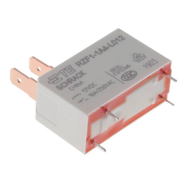
Power PCB Relay RZF
n
1 pole, 16A, 1 form A (NO)
Coil power 530mW
n Reinforced insulation (EN 61810, 60335, 60730)
n Ambient temperature up to 85°C
n Quick connect terminals for load
n Low mounted height of 17.9mm (27.6mm with quick connects)
n WG version with material in acordance with IEC 60335-1
n
Typical applications
Microwave ovens, water heaters, ovens, industrial equipment.
Approvals
VDE 40046175, UL E214025, CQC 17002175064
Technical data of approved types on request.
Contact Data
Contact arrangement
1 form A (NO)
Rated voltage
250VAC
Max. switching voltage
400VAC
Rated current
16A
Limited making current,
form A contact, max. 4 s, duty factor 10%
16A
Switching power
4000VA
Contact material
AgNi
Min. recommended contact load
100mA, 5VDC
Frequency of operation, with/without load
360/18000h-1
Operate/release time max.
8ms/6ms
Bounce time max.
4ms
Electrical endurance
16A, 250VAC, resistive, 23°C
100x103 ops.
16A, 250VAC, resistive, 85°C
50x103 ops.
Contact ratings
16A, 250VAC, resistive, 23°C, 100x103 ops.
16A, 250VAC, resistive, 85°C, 100x103 ops.
Mechanical endurance
10x106 operations
Coil Data
Coil voltage range
Coil operative range, IEC 61810
Coil insulation system according UL
Z
5 to 48VDC
2
class F
Coil versions, DC coil
Coil
Rated
Operate
Release
Coil
Rated coil
code voltage voltage voltage
resistance power
VDC VDC VDC
Ω±10%
mW
005 5 3.5 0.5 47.2 530
006 6 4.2 0.6 66.6 530
009 9 6.3 0.9 152.8 530
012 12 8.4 1.2 271.7 530
018 18 12.6 1.8 611 530
024 24 16.8 2.4 1086 530
048 48 33.6 4.8 4347 530
All figures are given for coil without pre-energization, at ambient temperature +23°C.
Coil Operating Range
Cycles
Electrical endurance
107
250VAC
resistive load
AgNi 90/10
106
105
104
0 2 4 6 8 10 12 14 16 18
Switching current [A]
01-2018, Revised
www.te.com
© 2018 TE Connectivity Ltd. family
of companies. All rights reserved.
Catalog and product specification according
to IEC 61810-1 and to be used only together
with the ‘Definitions’ section.
Catalog and product data is subject to the
terms of the disclaimer and all chapters of
the ‘Definitions’ section, available at
http://relays.te.com/definitions
Catalog product data, ‘Definitions’ section,
application notes and all specifications are
subject to change.
1
�General Purpose
Power PCB Relays
Power PCB Relay RZF
Insulation Data
Initial dielectric strength
between open contacts
between contact and coil
Initial surge withstand voltage
between contact and coil
Clearance/creepage
between contact and coil
Material group of insulation parts
Tracking index of relay base
(Continued)
Other Data
1000Vrms
5000Vrms
10000V
≥ 5.5/8mm
III
PTI 300
Dimensions
Material compliance: EU RoHS/ELV, China RoHS, REACH, Halogen content
refer to the Product Compliance Support Center at
www.te.com/customersupport/rohssupportcenter
Resistance to heat and fire
According EN 60335-1, par. 30
Ambient temperature
-40 to 85°C
Category of environmental protection
IEC 61810
RTII - flux proof
Vibration resistance (functional), 3 to 100Hz
>20g
Shock resistance (functional)
>10g
Shock resistance (destrictive)
>100g
Terminal type PCB-THT, quick connect for load side
Weight 11g
Resistance to soldering heat THT
IEC 60068-2-20
270°C/10s
Packaging/unit
tube/20 pcs.
box/500 pcs.
Terminal assignment
Bottom view on solder pins
PCB layout
Bottom view on solder pins
2
01-2018 Revised
www.te.com
© 2018 TE Connectivity Ltd. family
of companies. All rights reserved.
Catalog and product specification according
to IEC 61810-1 and to be used only together
with the ‘Definitions’ section.
Catalog and product data is subject to the
terms of the disclaimer and all chapters of
the ‘Definitions’ section, available at
http://relays.te.com/definitions
Catalog product data, ‘Definitions’ section,
application notes and all specifications are
subject to change.
�General Purpose
Power PCB Relays
Power PCB Relay RZF (Continued)
Product code structure
Typical product code
RZF 1 -1A 4 -L 012
000
Type
RZF
Power PCB Relay RZF
Version
1
16A, 3.5mm pinning, 4 PCB pins
Contact configuration
1A
1 form A (NO) contact
Contact material
4 AgNi 90/10
6 AgNi 90/10, special version
Coil version
L
DC coil, 530mW
Coil voltage
Coil code: please refer to coil versions table
Suffix
000 Standard, RT II, Reinforced flux proof, IEC 60335-1 Compliant
Other Special
Note: May be followed by up to five additional characters for manufacturer internal identification.
Product code
Version
Contact
Cont.material Coil power
Coil voltage
Sealing
Part number
RZF1-1A4-L005
4 PCB pins
1 form A (NO) AgNi 90/10 (std.)
530mW
5VDC
Flux proof
1833011-1
RZF1-1A4-L006
6VDC
1833011-2
RZF1-1A4-L009
9VDC
1833011-3
RZF1-1A4-L012
12VDC
1833011-4
RZF1-1A4-L018
18VDC
1833011-5
RZF1-1A4-L024
24VDC
1833011-6
RZF1-1A4-L048
48VDC
1833011-7
RZF1-1A6-L005
AgNi 90/10 (spl.)
5VDC
2-1833011-8
RZF1-1A6-L006
6VDC
1-1833011-5
RZF1-1A6-L009
9VDC
1-1833011-6
RZF1-1A6-L012
12VDC
1-1833011-7
RZF1-1A6-L018
18VDC
1-1833011-8
RZF1-1A6-L024
24VDC
1-1833011-9
RZF1-1A6-L048
48VDC
2-1833011-0
01-2018, Revised
www.te.com
© 2018 TE Connectivity Ltd. family
of companies. All rights reserved.
Catalog and product specification according
to IEC 61810-1 and to be used only together
with the ‘Definitions’ section.
Catalog and product data is subject to the
terms of the disclaimer and all chapters of
the ‘Definitions’ section, available at
http://relays.te.com/definitions
Catalog product data, ‘Definitions’ section,
application notes and all specifications are
subject to change.
3
�General Purpose
Power PCB Relays
Power PCB Relay RZF (Continued)
te.com
TE Connectivity and TE connectivity (logo) are trademarks.
Other products, logos and company namesmentioned herein may be trademarks of their respective owners.
The information given herein, including drawings, illustrations and schematics which are intended for illustration
purposes only, is believe to be reliable. However, TE Connectivity makes no warranties as to its accuracy or
completeness and disclaims any liability in connection with its use. TE Connectivity’s obligations shall only be as set
forth in TE Connectivity’s Standard Terms and Conditions of Sale for this product and in no case will TE Connectivity
be liable for any incidental, indirect or consequential damages arising out of the sale, resale, use or misuse of the
product. Users of TE Connectivity products should make their own evaluation to determine the suitability of each
such product for the specific application.
4
01-2018 Revised
www.te.com
© 2018 TE Connectivity Ltd. family
of companies. All rights reserved.
Catalog and product specification according
to IEC 61810-1 and to be used only together
with the ‘Definitions’ section.
Catalog and product data is subject to the
terms of the disclaimer and all chapters of
the ‘Definitions’ section, available at
http://relays.te.com/definitions
Catalog product data, ‘Definitions’ section,
application notes and all specifications are
subject to change.
�


 工商网监
湘ICP备2023018690号
工商网监
湘ICP备2023018690号

