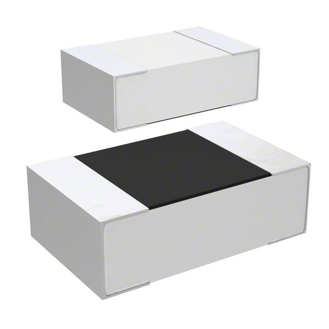
Trimmable Thick Film Chip Resistor
Type TCR Series
Key Features
Suitable for
laser fine tune
Small size and
light weight
Highly reliable
multilayer
electrode
construction
Compatible
with all
soldering
process
Applications
Tuner
Mobile Phone
Camcorder
Portable
Audio
This Ruthenium based trimmable thick film chip resistor, suitable for laser fine
tuning is ideal for use in circuits where a variable resistor might otherwise be
used.
Characteristics – Electrical
Size
0402
0603
0805
1206
1210
2010
2512
Power
Rating
@70°C
0.0625W
0.1W
0.125W
0.25W
0.3W
0.75W
1W
Max.
Operating
Voltage
50V
50V
150V
200V
200V
200V
250V
Max.
Overload
Voltage
100V
100V
300V
400V
400V
400V
500V
Tolerance
Resistance
Range
Ω~
+0 ~ -10
+0 ~ -20
+0 ~ -30
MΩ
Ω ~ 9.
Ω ~ MΩ
1M02 ~ MΩ
TCR
(ppm/°C)
±200
±200
±100
±200
Photo Sensor
Operating Temperature range -55 ~ +155°C
Portable
Measuring
Equipment
Operating Voltage=√ P*R or Max. operating oltage listed a o e, whichever is
lower.
O erload Voltage= . *√ P*R or Max. o erload oltage listed a o e, hi he er
is lower.
Derating
1773287 Rev. B 10/2018
Dimensions in
millimetres unless
otherwise specified
Dimensions Shown for
reference purposes only.
Specifications subject to
change
For Email, phone or live chat,
go to: www.te.com/help
Trimmable Thick Film Chip Resistor
Environmental Characteristics
Item
Requirement
Temperature Coefficient
of Resistance
(T.C.R.)
As Spec.
Short Time Overload
Insulation Resistance
Ω
≥10G
Endurance
± . %+ .
Ω
Damp Heat with Load
± . %+ .
Ω
Dry Heat
± . %+ .
Ω
. %+ .
Ω
Bending Strength
Solderability
Resistance to Soldering
Heat
Voltage Proof
1773287 Rev. B 10/2018
± . %+ .
Dimensions in
millimetres unless
otherwise specified
95% min. coverage
± . %+ .
Ω
No breakdown or
flashover
Dimensions Shown for
reference purposes only.
Specifications subject to
change
Test Methods
JIS-C-5201-1 4.8
IEC-60115-1 4.8
-55°C~+125°C,
25°C is the reference
temperature
JIS-C-5201-1 4.13
IEC-60115-1 4.13
RCWV*2.5 or Max.
Overload Voltage
whichever is lower for 5
seconds
JIS-C-5201-1 4.6
IEC-60115-1 4.6
Max. Overload Voltage
for 1 minute
JIS-C-5201-1 4.25
IEC-60115-1 4.25.1
70±2°C, RCWV for 1000
hrs ith . hrs ON
and . hr OFF
JIS-C-5201-1 4.24
IEC-60115-1 4.24
40±2°C, 90~95% R.H.
RCWV for 1000 hrs with
. hrs ON and . hr
OFF
JIS-C-5201-1 4.23
IEC-60115-1 4.23.2
at +125/+155°C for 1000
hrs
JIS-C-5201-1 4.33
IEC-60115-1 4.33
Bending once for 5
seconds
2010, 2512 sizes: 2mm
Other sizes: 3mm
JIS-C-5201-1 4.17
IEC-60115-1 4.17
245±5°C for 3 seconds
JIS-C-5201-1 4.18
IEC-60115-1 4.18
260±5°C for 10 seconds
JIS-C-5201-1 4.7
IEC-60115-1 4.7
1.42 times Max.
Operating Voltage for 1
minute
For Email, phone or live chat,
go to: www.te.com/help
Trimmable Thick Film Chip Resistor
Environmental Characteristics (cont.)
Item
Requirement
Individual leaching area
≦5%
Total leaching area
≦10%
Leaching
Rapid Change of
Temperature
± . %+ .
Test Methods
JIS-C-5201-1 4.18
IEC-60068-2-58 8.2.1
260±5°C for 30 seconds
JIS-C-5201-1 4.19
IEC-60115-1 4.19
-55°C to +125/+155°C, 5
cycles
Ω
RCWV Rated Continuous Working Voltage =√ P*R or Max. Operating Voltage
whichever is lower.
Storage Temperature: 15~28°C; Humidity < 80%RH
Construction and Dimensions
1
2
3
4
1773287 Rev. B 10/2018
Alumina Substrate
Bottom Electrode
Top Electrode
Edge Electrode
5
6
7
8
Barrier Layer
External Electrode
Resistor Layer
Primary Overcoat
Size
L
(mm)
W
(mm)
T
(mm)
D1
(mm)
D2
(mm)
0402
0603
0805
1206
1210
2010
2512
1.00±0.05
1.60±0.10
2.00±0.10
3.10±0.10
3.10±0.10
5.00±0.10
6.35±0.10
0.50±0.05
0.80±0.10
1.25±0.10
1.55±0.10
2.60±0.15
2.50±0.15
3.10±0.15
0.35±0.05
0.45±0.10
0.50±0.10
0.55±0.10
0.55±0.10
0.55±0.10
0.55±0.10
0.20±0.10
0.30±0.20
0.35±0.20
0.50±0.25
0.50±0.25
0.60±0.25
0.60±0.25
0.20±0.10
0.30±0.20
0.40±0.20
0.50±0.20
0.50±0.20
0.50±0.20
0.50±0.20
Dimensions in
millimetres unless
otherwise specified
Dimensions Shown for
reference purposes only.
Specifications subject to
change
Weight
(g)
(1000pcs)
0.620
2.042
4.368
8.947
15.959
24.241
39.448
For Email, phone or live chat,
go to: www.te.com/help
Trimmable Thick Film Chip Resistor
Recommended Land Pattern
Size
0402
0603
0805
1206
1210
2010
2512
A
(mm)
0.50
0.90
1.20
2.00
2.00
3.80
3.80
B
(mm)
0.45
0.60
0.70
0.90
0.90
0.90
1.60
C
(mm)
0.60
0.90
1.30
1.60
2.80
2.80
3.50
Soldering Condition
(1) Time of IR reflow soldering at maximum temperature point 260°C:10s
(2) Time of wave soldering at maximum temperature point 260°C:10s
(3) Time of soldering iron at maximum temperature point 410°C:5s
1773287 Rev. B 10/2018
Dimensions in
millimetres unless
otherwise specified
Dimensions Shown for
reference purposes only.
Specifications subject to
change
For Email, phone or live chat,
go to: www.te.com/help
Trimmable Thick Film Chip Resistor
Packaging
Reel Specification
Size
Tape
Type
Qty
Reel
Tape
Width
Reel
Nom.
ØA
(mm)
ØB
(mm)
0402
0603
0805
1206
1210
2010
2512
Paper
Paper
Paper
Paper
Paper
Emboss
Plastic
10K
5K
5K
5K
5K
4K
4K
8mm
8mm
8mm
8mm
8mm
12mm
12mm
7 inch
7 inch
7 inch
7 inch
7 inch
7 inch
7 inch
178.5±1.5
178.5±1.5
178.5±1.5
178.5±1.5
178.5±1.5
178.5±1.5
178.5±1.5
E
±0.10
1.75
1.75
1.75
1.75
1.75
F
±0.05
3.50
3.50
3.50
3.50
3.50
⁺¹/₋
⁺¹/₋
⁺¹/₋
⁺¹/₋
⁺¹/₋
⁺¹/₋
⁺¹/₋
ØC
(mm)
W
(mm)
T
(mm)
13.0±0.2
13.0±0.2
13.0±0.2
13.0±0.2
13.0±0.2
13.0±0.2
13.0±0.2
9.0±0.5
9.0±0.5
9.0±0.5
9.0±0.5
9.0±0.5
13.0±0.5
13.0±0.5
12.5±0.5
12.5±0.5
12.5±0.5
12.5±0.5
12.5±0.5
15.5±0.5
15.5±0.5
Paper Tape Specification.
Dimensions (mm)
Size
0402
0603
0805
1206
1210
1773287 Rev. B 10/2018
A
±0.10
0.65
1.10
1.60
1.90
2.90
B
1.15±0.10
1.90±0.10
2.40±0.20
3.50±0.20
3.50±0.20
Dimensions in
millimetres unless
otherwise specified
W
±0.20
8.0
8.0
8.0
8.0
8.0
P
±0.10
4.00
4.00
4.00
4.00
4.00
Dimensions Shown for
reference purposes only.
Specifications subject to
change
P
±0.05
2.00
4.00
4.00
4.00
4.00
P
±0.05
2.00
2.00
2.00
2.00
2.00
ØD
+0.1/-0
1.50
1.50
1.50
1.50
1.50
T
±0.10
0.45
0.70
0.85
0.85
0.85
For Email, phone or live chat,
go to: www.te.com/help
Trimmable Thick Film Chip Resistor
Embossed Plastic Tape Specification
Dimensions (mm)
Size
2010
2512
A
±0.10
2.8
3.5
B
±0.10
5.5
6.7
W
±0.30
12.0
12.0
E
±0.10
1.75
1.75
F
±0.05
5.5
5.5
P
±0.10
4.00
4.00
P
±0.10
4.00
4.00
P
±0.05
2.00
2.00
ØD
+0.1/-0
1.50
1.50
T
±0
1.2
1.2
How To Order
TCR
Common Part
TCR
1773287 Rev. B 10/2018
Dimensions in
millimetres unless
otherwise specified
0805
Size
0402
0603
0805
1206
1210
2010
2512
N
Resistance Tolerance
1K5
Resistance
N: 0 ~ -10%
P: 0 ~ -20%
Q: 0 ~ -30%
1R2: 1.2Ω
100R: 100Ω
3K3: 3.3KΩ
100K: 100KΩ
1M5: 1.5MΩ
M: MΩ
Dimensions Shown for
reference purposes only.
Specifications subject to
change
For Email, phone or live chat,
go to: www.te.com/help
很抱歉,暂时无法提供与“TCR1206N270K”相匹配的价格&库存,您可以联系我们找货
免费人工找货