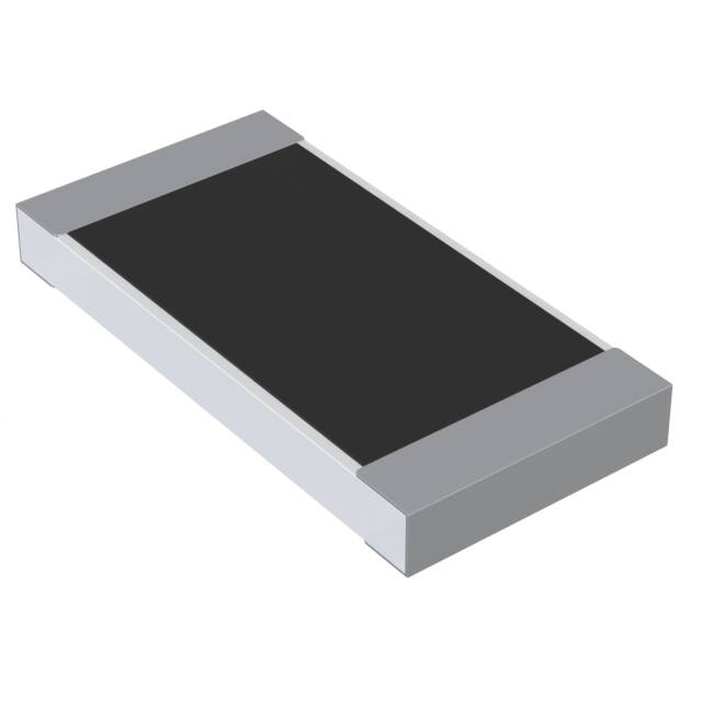
SMD Current Sense Metal Chip Resistor
Type TLM Series
Key Features
Low resistance
resistor for
current detection
Small size to
power ratio
Metal foil
construction
ensures high
reliability and
performance with
very low and
stable TCR
Designed for
current sense
circuits in power
electronic
systems
Terminal finish
matte Sn over Ni
TE Connectivity is pleased to introduce this low ohmic metal chip resistor
designed for current sense circuits in power electronic systems. Supplied as
standard on tape and reel for automatic insertion processes.
Characteristics – Electrical
Type
Power Rating @
70°C
TLM 1J
0.125W
TLM 2A
0.25W
TLM 2B
0.5W
TLM 2H
0.75W
TLM 3A
1W
Operating Temp.
Range
Resistance Range (mΩ)
±1%
±2%
±5%
10 - 19
20 - 100
10 - 19
20 - 100
10 – 19
-55~+55°C
20 - 100
10 – 19
20 - 100
10 – 19
20 - 100
TCR (PPM/°C)
±100
±50
±100
±100
±50
±100
±100
±50
±100
±100
±50
±100
±100
±50
±100
Operating Voltage=√(P*R) ; Overload Voltage=2.5*√(P*R) ; Operating Current=√(P/R)
1773269-1 CIS WR 01/2015
Dimensions in
millimetres unless
otherwise specified
Dimensions Shown for
reference purposes only.
Specifications subject to
change
For Email, phone or live chat,
go to: www.te.com/help
�SMD Current Sense Metal Chip Resistor
Power derating curve
For resistors operated in ambient temperatures above 70°C, power rating
must be derated in accordance with this curve.
Environmental Characteristics
Item
Temperature Coefficient of
Resistance (TCR)
Short Term Overload
Insulation Resistance
Endurance
Requirement
As Spec.
Damp Heat with Load
±(1.0%+0.05Ω)
Dry Heat
Bending Strength
±(0.5%+0.05Ω)
As Spec.
Solderability
Resistance to Soldering Heat
Voltage Proof
Leaching
95% min. coverage
±(0.5%+0.05Ω)
No breakdown or flashover
Individual leaching area
≦5%
Total leaching area ≦10%
±(0.5%+0.05Ω)
Rapid Change of
Temperature
±(0.5%+0.05Ω)
≧10G
±(1.0%+0.05Ω)
Test Method
-55°C~+125°C, 25°C is the reference
temperature
5 X Rated Power for 5 seconds
Max. overload voltage for 1 minute
70±2°C, Max. working voltage for 1000
hrs with 1.5 hrs “ON” and 0.5 hrs
“OFF”
40±2°C, 90~95% R.H. Max. working
voltage for 1000 hrs with 1.5 hrs “ON”
and 0.5 hrs “OFF”
at +155°C for 1000 hrs
Bending once for 5 seconds 2010, 2512
sizes: 2mm Other sizes: 3mm
245±5°C for 3 seconds
260±5°C for 10 seconds
1.42 times RCWV (RMS) for 1 minute
260±5°C for 30 seconds
-55°C to +155°C, 5 cycles
Reference Standards: IEC 60115-1, 60068-2-58; JIS-C 5201-1
Storage Temperature: 25±3°C; Humidity < 80%RH
1773269-1 CIS WR 01/2015
Dimensions in
millimetres unless
otherwise specified
Dimensions Shown for
reference purposes only.
Specifications subject to
change
For Email, phone or live chat,
go to: www.te.com/help
�SMD Current Sense Metal Chip Resistor
Construction:
1
2
3
4
Alumina Substrate
Bottom Electrode (Cu)
Top Electrode (NiCr)
Edge Electrode (NiCr)
5
6
7
8
Barrier Layer (Ni)
External Electrode (Sn)
Adhesive (Acrylic)
Resistor Layer (Alloy)
9
10
Primary Overcoat (Epoxy)
Marking (Epoxy)
Dimensions
Type
TLM 1J
TLM 2A
TLM 2B
TLM 2H
TLM 3A
Resistance
Range (mΩ)
10 – 29
30 - 100
10 – 29
30 - 100
10 - 29
30 - 100
10 - 29
30 - 100
10 – 29
30 - 100
L
W
T
D1
D2
1.55±0.10
1.55±0.10
2.00±0.15
2.00±0.15
3.05±0.15
3.05±0.15
5.00±0.20
5.00±0.20
6.30±0.20
6.30±0.20
0.85±0.10
0.85±0.10
1.25±0.15
1.25±0.15
1.55±0.15
1.55±0.15
2.50±0.20
2.50±0.20
3.15±0.20
3.15±0.20
0.40±0.10
0.40±0.10
0.55±0.10
0.52±0.10
0.58±0.15
0.55±0.15
0.58±0.15
0.55±0.15
0.58±0.15
0.55±0.15
0.30±0.15
0.30±0.15
0.30±0.20
0.30±0.20
0.50±0.25
0.50±0.25
0.60±0.30
0.60±0.30
0.60±0.30
0.60±0.30
0.45±0.15
0.35±0.15
0.50±0.20
0.35±0.20
0.90±0.25
0.60±0.25
1.50±0.30
0.90±0.30
1.80±0.30
1.20±0.30
Recommended Land Pattern:
Type
TLM1J
TLM2A
TLM2B
TLM2H
TLM3A
1773269-1 CIS WR 01/2015
Dimensions in
millimetres unless
otherwise specified
Resistance
Range (mΩ)
10 – 29
30 - 100
10 – 29
30 - 100
10 - 29
30 - 100
10 - 29
30 - 100
10 – 29
30 - 100
Dimensions Shown for
reference purposes only.
Specifications subject to
change
A
B
C
0.40
0.70
0.80
1.00
0.9
1.50
1.70
2.80
2.30
3.60
1.20
1.05
1.10
1.00
1.70
1.40
2.35
1.80
2.90
2.25
0.50
0.90
1.35
1.35
1.70
1.70
2.50
2.50
3.10
3.10
For Email, phone or live chat,
go to: www.te.com/help
�SMD Current Sense Metal Chip Resistor
Packaging
Packaging Quantity and Reel Specification:
Type
ΦA
ΦB
ΦC
W
T
Paper
Tape (EA)
TLM1J
TLM2A
TLM2B
TLM2H
TLM3A
178.0±1.0
178.0±1.0
178.0±1.0
178.0±1.0
178.0±1.0
60.0±1.0
60.0±1.0
60.0±1.0
60.0±1.0
60.0±1.0
13.5±0.7
13.5±0.7
13.5±0.7
13.5±0.7
13.5±0.7
9.5±0.1
9.5±0.1
9.5±0.1
13.5±1.0
13.5±1.0
11.5±1.0
11.5±1.0
11.5±1.0
15.5±1.0
15.5±1.0
5,000
5,000
5,000
-
Embossed
Plastic Tape
(EA)
4,000
4,000
Paper Tape Specifications
Type
A
B
W
E
F
P0
P1
P2
ΦD0
T
TLM1J
1.10
±0.10
1.60
±0.10
1.90
±0.10
1.90
±0.10
2.40
±0.20
3.50
±0.20
8.0
±0.20
8.0
±0.20
8.0
±0.20
1.75
±0.10
1.75
±0.10
1.75
±0.10
3.50
±0.05
3.50
±0.05
3.50
±0.05
4.00
±0.10
4.00
±0.10
4.00
±0.10
4.00
±0.05
4.00
±0.05
4.00
±0.05
2.00
±0.05
2.00
±0.05
2.00
±0.05
1.50
+0.1 -0
1.50
+0.1 -0
1.50
+0.1 -0
0.70
±0.10
0.85
±0.10
0.85
±0.10
TLM2A
TLM2B
1773269-1 CIS WR 01/2015
Dimensions in
millimetres unless
otherwise specified
Dimensions Shown for
reference purposes only.
Specifications subject to
change
For Email, phone or live chat,
go to: www.te.com/help
�SMD Current Sense Metal Chip Resistor
Embossed Plastic Tape Specifications
Type
A
B
W
E
F
P0
P1
P2
ΦD0
T
TLM2H
2.80
±0.10
3.50
±0.10
5.50
±0.10
6.700
±0.20
12.0
±0.10
12.0
±0.20
1.75
±0.10
1.75
±0.10
5.50
±0.05
5.50
±0.05
4.00
±0.05
4.00
±0.05
4.00
±0.10
4.00
±0.10
2.00
±0.05
2.00
±0.05
1.50
±0.10
1.50
±0.10
1.00
±0.20
1.00
±0.20
TLM3A
How To Order
TLM
Common
Part
TLM
1773269-1 CIS WR 01/2015
2A
Size
1J – 0603
2A – 0805
2B – 1206
2H – 2010
3A – 2512
Dimensions in
millimetres unless
otherwise specified
TCR
E
R01
Resistance
Value
D – 50PPM
10mΩ - R01
E–
100PPM
100mΩ R10
Dimensions Shown for
reference purposes only.
Specifications subject to
change
J
Tolerance
F - 1%
J - 5%
TD
Pack Style
TD – Reel 5K
(0603,0805,
1206)
TE – Reel 4K
(2010, 2512)
For Email, phone or live chat,
go to: www.te.com/help
�
很抱歉,暂时无法提供与“TLM2HER10JTE”相匹配的价格&库存,您可以联系我们找货
免费人工找货