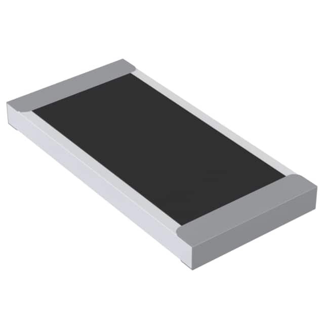
SMD Low Ohmic – Current Sense Resistors
Key Features
Type TLR Series
Up to 3 Watt
at 80°C
Supplied on
Tape
Ideal for
Current
Detection
12:06, 20:10
and 25:12
Packages
Available
TE Connectivity (TE) is pleased to offer this unique High Power, metal chip
resistor for current sensing positions. It has a special metal resistive element
and suitable barrier layers beneath the solder to prolong terminal life. Following
the developments by semiconductor manufacturers in the production of a range
of IC's for battery charge management and low voltage power supplies, the TLR
Series satisfies the demand for a low ohmic shunt resistor to act as a current
sensor. It has particular applications in the automotive industry for sensing in
EMU's.
Characteristics – Electrical (Standard)
Size
1206
1206
2512
2512
2512
2512
Power Rating
@ 70°C
±1%
1W
1W
1W
1W
1W
1W
Resistance Range (mΩ)
±3%
±5%
0.5
0.75 ~ 10
0.5, 0.75, 1, 1.5, 2
6, 6.5, 7
4, 5, 10
2.5, 3
TCR
(PPM/°C)
±200
±50
±50
±75
±100
±150
Operating Temperature Range: -55 ~ 170°C
Operating Current = √(P/R), Operating Voltage = √(P*R)
1773449-3 Rev. J 08/2020
Dimensions in
millimetres unless
otherwise specified
Dimensions Shown for
reference purposes only.
Specifications subject to
change
For Email, phone or live chat,
go to: www.te.com/help
�SMD Low Ohmic – Current Sense Resistors
Characteristics – Electrical (High Power)
Resistance Range (mΩ)
Power Rating
@ 70°C
±1%
±3%
±5%
2010
1.5W
0.5
2010
1.5W
0.75 ~ 10
2512
2W
0.5, 0.75, 1, 1.5, 2
2512
2W
6, 6.5, 7
2512
2W
4, 5, 10
2512
2W
2.5, 3
2512
3W
0.5, 0.75, 1, 1.5, 2
Operating Temperature Range: -55 ~ 170°C
Size
TCR
(PPM/°C)
±100
±50
±50
±75
±100
±150
±50
Operating Current = √(P/R), Operating Voltage = √(P*R)
Construction and Dimensions
1
2
Solder Plating
Alloy plate
Value
0.5mΩ ~ 3mΩ
3.5mΩ ~ 10mΩ
3 Barrier Layer
4 Overcoat
Material
Manganese, Copper
Aluminium, Iron, Chromium
NB. 1206 and 2010 size – No Coating / Marking
1773449-3 Rev. J 08/2020
Dimensions in
millimetres unless
otherwise specified
Dimensions Shown for
reference purposes only.
Specifications subject to
change
For Email, phone or live chat,
go to: www.te.com/help
�SMD Low Ohmic – Current Sense Resistors
Dimensions:
Part number
TLR2B10FR0005*TDG
0.5
TLR2B10DR00075*TDG
0.75
TLR2B10D**TDG
1.0, 3.5,
4.0, 5.0, 6.0
2.0, 3.0, 10
TLR2B10D**TDG
TLR2B10D**TDG
1773449-3 Rev. J 08/2020
Resistance
Ω
TLR2H15ER0005*TDG
1.2, 1.5,
7.0, 8.0, 9.0
0.5
TLR2H15DR00075*TDG
0.75
TLR2H15D**TDG
1.0, 1.5
TLR2H15D**TDG
TLR2H15D**TDG
2.0, 6.0,
7.0, 8.0
3.0, 3.5
TLR2H15D**TDG
4.0, 5.0, 5.5
TLR2H15D**TDG
9.0, 10
TLR3A**DR0005TDG
0.5
TLR3A**DR00075TDG
0.75
TLR3A**DR001TDG
1.0
TLR3A**DR0015TDG
1.5
TLR3A**DR002TDG
2.0
TLR3A**KR0025TDG
2.5
TLR3A**KR003TDG
3.0
TLR3A**ER004TDG
4.0
TLR3A**ER005TDG
5.0
TLR3A**WR006TDG
6.0
TLR3A**WR0065TDG
6.5
TLR3A**WR007TDG
7.0
TLR3A**ER010TDG
10
Dimensions in
millimetres unless
otherwise specified
L
W
3.20
±0.25
3.20
±0.25
3.20
±0.25
3.20
±0.25
3.20
±0.25
5.08
±0.25
5.08
±0.25
5.08
±0.25
5.08
±0.25
5.08
±0.25
5.08
±0.25
5.08
±0.25
6.35
±0.254
6.35
±0.254
6.35
±0.254
6.35
±0.254
6.35
±0.254
6.35
±0.254
6.35
±0.254
6.35
±0.254
6.35
±0.254
6.35
±0.254
6.35
±0.254
6.35
±0.254
6.35
±0.254
1.60
±0.10
1.60
±0.10
1.60
±0.10
1.60
±0.10
1.60
±0.10
2.54
±0.15
2.54
±0.15
2.54
±0.15
2.54
±0.15
2.54
±0.15
2.54
±0.15
2.54
±0.15
3.18
±0.254
3.18
±0.254
3.18
±0.254
3.18
±0.254
3.18
±0.254
3.18
±0.254
3.18
±0.254
3.18
±0.254
3.18
±0.254
3.18
±0.254
3.18
±0.254
3.18
±0.254
3.18
±0.254
Dimensions Shown for
reference purposes only.
Specifications subject to
change
T
0.60
±0.20
0.60
±0.20
0.60
±0.20
0.60
±0.20
0.60
±0.20
0.60
±0.20
0.60
±0.20
0.60
±0.20
0.60
±0.20
0.60
±0.20
0.60
±0.20
0.60
±0.20
1.25
±0.20
0.75
±0.20
0.65
±0.20
0.45
±0.20
0.35
±0.20
0.65
±0.20
0.55
±0.20
0.45
±0.20
0.35
±0.20
0.32
±0.20
0.30
±0.20
0.27
±0.20
0.25
±0.20
D
1.35
±0.25
1.23
±0.25
1.10
±0.25
0.60
±0.25
0.90
±0.25
2.17
±0.25
2.04
±0.25
1.84
±0.25
1.54
±0.25
1.04
±0.25
1.84
±0.25
1.29
±0.25
1.30
±0.38
1.30
±0.38
1.30
±0.38
1.30
±0.38
1.30
±0.38
1.30
±0.38
1.30
±0.38
1.30
±0.38
1.30
±0.38
1.30
±0.38
1.30
±0.38
1.30
±0.38
1.30
±0.38
Weight
(g)
1000 pcs
22.6
22.6
22.6
22.6
22.6
42.3
42.3
42.3
42.3
42.3
42.3
42.3
184.11
131.11
110.85
67.16
49.30
97.95
83.49
62.59
49.84
41.76
35.85
34.01
25.97
For Email, phone or live chat,
go to: www.te.com/help
�SMD Low Ohmic – Current Sense Resistors
Marking – 2512 only
Resistance (3 digit)
Resistance
Codes
0.5mΩ
M50
0.75mΩ
M75
Resistance (4 Digit)
Resistance
Codes
1mΩ
R001
2mΩ
R002
7mΩ
R007
10mΩ
R010
Solder Profile
Reflow
Derating Curve
1773449-3 Rev. J 08/2020
Dimensions in
millimetres unless
otherwise specified
Dimensions Shown for
reference purposes only.
Specifications subject to
change
For Email, phone or live chat,
go to: www.te.com/help
�SMD Low Ohmic – Current Sense Resistors
Environmental Characteristics
Item
Requirement
Test Method
Temperature Coefficient of
Resistance (T.C.R.)
As Spec.
Short Term Overload
±0.5%
Endurance
±1%
Dry Heat
±1%
Solderability
95% Minimum Coverage
Resistance to Soldering
Heat
Thermal Shock
±0.5%
MIL-STD-202 Method 304
+25°C ~125°C, 25°C is the
reference temperature
JIS-C-5201-1 5.5
5*rated power for 5
seconds
MIL-STD-202 Method 108A
70±2°C, RCWV for 1000 hrs
with .5 hrs ON a d .5 hr
OFF
JIS-C-5201-1 7.2
at +170°C for 1000 hrs
MIL-STD-202 Method 208H
245±5°C for 3 seconds
MIL-STD-202 Method 210E
260±5°C for 10 seconds
MIL-STD-202 Method 107G
-55°C ~ 150°C, 100 cycles
±0.5%
Packaging
Reel Dimensions (mm)
Tape
Width
8mm
12mm
Reel
Diameter
7 Inch
ØA
ØB
ØC
W
T
178.5±1.5
60 ¹ ⁰
60±1.0
13.0±0.2
9.0±0.5
13.0±1.0
12.5±0.5
15.5±0.5
Embossed Plastic Tape specification
1773449-3 Rev. J 08/2020
Dimensions in
millimetres unless
otherwise specified
Dimensions Shown for
reference purposes only.
Specifications subject to
change
For Email, phone or live chat,
go to: www.te.com/help
�SMD Low Ohmic – Current Sense Resistors
Size
2B
2H
3A
Res
Ω
All
All
≤ .75
1-10
A
±0.1
1.90
2.85
B
±0.1
3.60
5.55
W
±0.2
8.0
12.0
E
±0.1
1.75
1.75
F
±0.5
3.5
5.5
P
±0.1
4.0
4.0
P
±0.1
4.0
4.0
P
±.05
2.0
2.0
ØD
±.05
1.55
1.55
ØD
min
1.0
1.4
3.40
6.75
12.0
1.75
5.5
4.0
4.0
2.0
1.55
1.4
T
±0.2
0.87
0.85
1.45
0.81
Qty
2000
2000
2000
1. The cumulative tolerance of 10 sprockets hole pitch is ±0.2mm.
2. Carrier camber shall be not more than 1mm per 100mm through a length of 250mm.
3. A & B measured 0.3mm from the bottom of the packet
4. T measured at a point on the inside bottom of the packet to the top surface of the carrier.
5. Pocket position relative to sprocket hole is measured as the true position of the pocket and not
the pocket hole.
Measurements
1. TLR3A 4-wire precision measurement
Equipment: ADEX AX-1152D DC Low Ohm Meter
Excitation Current: 3A (0.5mΩ~1.5 mΩ) 1A
Ω~
Ω
2. TLR3A 4-wire pad layout (recommended for precision current
sensing)
■Note: No circuits between pads to avoid short circuit
1773449-3 Rev. J 08/2020
Dimensions in
millimetres unless
otherwise specified
Dimensions Shown for
reference purposes only.
Specifications subject to
change
For Email, phone or live chat,
go to: www.te.com/help
�SMD Low Ohmic – Current Sense Resistors
3. TLR3A 2-wire pad layout
■ Note: No circuits between pads to avoid short circuit
4. TLR 2B 4-wire precision measurement
■Equipment: ADEX AX-1152D DC Low Ohm Meter
■Excitation Current: 1A (0.5mΩ~10mΩ)
5. TLR2B 4-wire pad layout (recommended for precision current sensing)
■Note: No circuits between pads to avoid short circuit
6. TLR2B 2-wire pad layout
■Note: No circuits between pads to avoid short circuit
1773449-3 Rev. J 08/2020
Dimensions in
millimetres unless
otherwise specified
Dimensions Shown for
reference purposes only.
Specifications subject to
change
For Email, phone or live chat,
go to: www.te.com/help
�SMD Low Ohmic – Current Sense Resistors
7. TLR2H 4-wire precision measurement
■ Equipment: ADEX AX-1152D DC Low Ohm Meter
■ Excitation Current: 1A (0.5mΩ~10mΩ)
8. TLR2H 4-wire pad layout (recommended for precision current sensing)
■ Note: No circuits between pads to avoid short circuit
9. TLR2H 2-wire pad layout
■ Note: No circuits between pads to avoid short circuit
How To Order
TLR
Common
Part
TLR –
Ultra Low
Ohm
Metal
Strip
Resistor
1773449-3 Rev. J 08/2020
2B
Size
2B – 1206
2H – 2010
3A – 2512
Dimensions in
millimetres unless
otherwise specified
10
*Power
Rating
D
**TCR
(PPM/°C)
R005
Resistance
Code
1.0 = 10
1.5 = 15
2.0 = 20
3.0 = 30
D = ±50
W = ±75
E = ±100
K = ±150
R0005 0.5mΩ
R0015 –
.5 Ω
R002 –
Ω
Dimensions Shown for
reference purposes only.
Specifications subject to
change
F
TDG
Tolerance
Packaging
J = ±5%
H = ±3%
F = ±1%
TDG =
2000 /
Reel
For Email, phone or live chat,
go to: www.te.com/help
�


 工商网监
湘ICP备2023018690号
工商网监
湘ICP备2023018690号
