D a ta S h e e t , R ev . 1 . 5 1, J u n e 20 0 7
TLE 7263E
I n t e g r a t e d H S - C A N , L IN , L D O a n d HS Switch System Basis Chip
Automotive Power
Never stop thinking.
�Integrated HS-CAN, LIN, LDO and HS Switch System Basis Chip
TLE 7263E
1
Features • • • • • • • • • • • • •
Overview
Two Low Drop Voltage Regulators Window watchdog Standard 16-bit SPI-interface Supports µController Stop Mode Sleep Mode (50µA) VBAT Monitoring and fail-safe output Overtemperature and short circuit protection Power on and undervoltage reset generator High side switch, 150 mA 4 Monitoring / wake-up inputs Exposed Pad Package AEC Qualified Green (RoHS Compliant) product
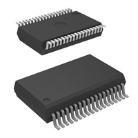
PG-DSO-36-24
HS CAN Transceiver • • • • • CAN data transmission rate up to 1 MBaud Low power mode management Supports sleep and receive-only modes Bus wake-up capability via CAN message Bus pins are short circuit proof to ground and battery voltage
LIN Transceiver • • • • • Single-wire transceiver Transmission rate up to 20 kBaud Compatible to LIN specification 1.3 and 2.0 Very low current consumption in Sleep Mode Short circuit proof to GND and battery
Type TLE 7263E
Data Sheet
Package PG-DSO-36-24
2
Marking
Rev. 1.51, 2007-06-22
�TLE 7263E
Overview Dual-Voltage Regulator • • • Low-dropout voltage regulator, dual voltage-supply V1, 150 mA, 5 V ±2% for external devices, e.g. microcontrollers V2, 150 mA, 5 V ±2% for internal CAN module and external devices.
Description The TLE 7263E is a monolithic integrated circuit in an enhanced power package. The IC is designed for CAN-LIN gateway applications. To support these applications the TLE 7263E covers smart power functions such as HSCAN transceiver and LIN transceiver for data transmission, dual low dropout voltage regulator (LDO) for external 5 V supply, and high-side switch as well as a 16-bit SPI (serial peripheral interface) to control and monitor the IC. There is also a window watchdog circuit with a reset feature, a fail-safe output, a voltage sensing input and a undervoltage reset feature implemented. The device offer low power modes in order to support modules directly connected to the battery (KL. 30). A wake-up from the low power mode is possible via a message on the bus or via the bi level sensitive monitoring/wake-up inputs. The integrated High-Side switch can also be used to periodically supply an external wake-up circuitry in the low power mode, by choosing a special function. The integrated bus transceivers offer a receive-only mode for software diagnosis functions. The IC is designed to withstand the severe conditions of automotive applications.
Data Sheet
3
Rev. 1.51, 2007-06-22
�TLE 7263E
Pin Configuration
2
Pin Configuration
GND GND NC LIN MTS GND OUTHS VS MON1 MON2 MON3 MON4 SI GND VCC1 VCC2 INT GND
1 2 3 4 5 6 7 8 9 10 11 12 13 14 15 16 17 18
36 35
GND TxDLIN RxDLIN FSO WKO CSN CLK DI DO STS RO RxDCAN TxDCAN GND CANL SPLIT CANH GND
TLE7263E DSO 36 - Exposed Pad
34 33 32 31 30 29
cooling tab (GND)
28 27 26 25 24 23 22 21 20 19
Pinnout_7263_SO-36EP
Figure 1
Pin Configuration (top view)
Data Sheet
4
Rev. 1.51, 2007-06-22
�TLE 7263E
Pin Configuration Table 1 Pin 9 10 11 12 8 Pin Definitions and Functions Symbol Function MON1, MON2, MON3, MON4 Monitoring / Wake-Up Inputs; bi level sensitive inputs used to monitor signals coming from, for example, an external switch panel; also used as wake-up input during cyclic sensing in low power modes (MON4 is exempted from “cyclic sense” as this input is permanently active) Power Supply Input; block to GND directly at the IC with ceramic capacitor; (ferrite recommended for better EMC behavior) Voltage Regulator Output (V1); 5 V supply; to stabilize block to GND with an external capacitor CQ ≥ 10 µF, ESR < 6 Ω Voltage Regulator Output (V2); 5 V supply; to stabilize block to GND with an external capacitor CQ ≥ 10 µF, ESR < 6 Ω Wake-Up Event Output; indicates wake up via monitoring inputs, CAN or LIN during Sleep or Stop Mode; active low; wake up sets device to Standby Mode Fail Safe Output; to supervise and control critical applications, high when watchdog is correctly served, low at any reset condition; active low Reset Output; open drain output, integrated pull-up, active low Sense Comparator Input; for monitoring of external voltages, to program the detection level connect external voltage divider Interrupt Output; output to monitor sense comparator input condition; input for enabling the Flash Programming Mode (voltage to be applied > 7 V) Master Termination Switch; output used to turn-on the termination/pull-up resistor of a LIN master LIN Transceiver Data Output; according to the ISO 9141 and LIN specification 1.3 and 2.0; push-pull output; LOW in dominant state LIN Transceiver Data Input; according to ISO 9141 and LIN specification 1.3 and 2.0
VS VCC1 VCC2
15
16
32
WKO
33
FSO
26 13
RO SI
17
INT
5 34
MTS RxDLIN
35
TxDLIN
Data Sheet
5
Rev. 1.51, 2007-06-22
�TLE 7263E
Pin Configuration Table 1 Pin 4 29 LIN DISPI Pin Definitions and Functions (cont’d) Symbol Function LIN Bus; Bus Line for the LIN interface, according to ISO 9141 and LIN specification 1.3 and 2.0 SPI Data Input; receives serial data from the control device; serial data transmitted to DI is a 16-bit control word with the Least Significant Bit (LSB) transferred first: the input has a pull-down and requires CMOS logic level inputs; DI will accept data on the falling edge of CLK-signal SPI Data Output; this tri-state output transfers diagnosis data to the control device; the output will remain 3-stated unless the device is selected by a low on Chip-Select-Not (CSN) SPI Clock Input; clock input for shift register; CLK has an internal pull-down and requires CMOS logic level inputs SPI Chip Select Not Input; CSN is an active low input; serial communication is enabled by pulling the CSN terminal low; CSN input should only be transitioned when CLK is low; CSN has an internal pull-up and requires CMOS logic level inputs
28
DOSPI
30 31
CLKSPI CSNSPI
7
OUTHS High Side Switch Output; controlled via SPI, in SBC Sleep Mode controlled by internal cyclic sense function when selected TxDCAN RxDCAN SPLIT CANH CANL STS CAN Transmit Data Input; integrated pull-up CAN Receive Data Output CAN Termination Output; to support the recessive voltage level of the bus lines CAN High Line Output CAN Low Line Input Send-to-Sleep; to switch the SBC back into low current mode during cyclic wake Ground
24 25 21 20 22 27
GND 1, 2, 6,14, 18,19, 23,36 3 EP NC EP
Not Connected Internally; leave open or connect to GND Exposed Pad; internally connected to GND; connect to GND on board
Data Sheet
6
Rev. 1.51, 2007-06-22
�TLE 7263E
Block Diagram
3
VS
Block Diagram
OUTHS Interrupt control STS CSN
Drive + Protection INT SI Early Warning VS S upervisor
SPI
CLK DI DO VCC1
Over Current Over voltage Band Gap
+
Oscillator Timebase Reset Generator + Window Watchdog
V CC1
RO FSO
LDO 1
V CC2 Over Current Over voltage
LDO 2
MON1 MON2 MON3 MON4 CANH CANL
Wake-Up Logic
HS-CAN Mode Control V CC1
Output Stage
Driver Temp.Protection
Diagnosis Logic WKO
+ timeout
TxDCAN VCC1
SPLIT MUX RxDCAN
HS-CAN Transceiver
Receiver + Bus Failure Detection VS LIN Mode Control
Vs
MTS
Driver 30 kOhm LIN Output Stage Temp.Protection
V CC1
TxDLIN
Receiver Filter / Wake-Up RxDLIN
LIN Transceiver
GND
blockdiagramm7263
Figure 2
Data Sheet
Functional Block Diagram
7 Rev. 1.51, 2007-06-22
�TLE 7263E
Features
4
Features
The TLE 7263E incorporates a lot of features, that are listed in Table 2 below. A short description of the features is given in “Operation Modes” on Page 9. Table 2 Feature Truth Table of the TLE 7263E SBC Active Mode ON ON ON ON ON ON ON OFF ON SBC Standby Mode ON ON/OFF ON ON ON ON ON ON OFF ON SBC Stop Mode ON ON/OFF ON ON/OFF ON ON ON ON ON ON ON OFF OFF OFF OFF active low wake-up interrupt active low wake-up interrupt active low early warning active low wake-up SBC Sleep Mode OFF OFF1) OFF OFF/[ON] OFF OFF ON OFF ON OFF ON OFF OFF OFF OFF low CAN RxD-only Mode ON ON ON ON ON ON ON ON OFF ON OFF OFF ON ON ON L/H
VCC, V1, 5 V VCC, V2, 5 V
Reset RO Fail Safe Output Sense input Monitoring pins HS-switch HS-cyclic-sense 16-bit SPI CAN/LIN wake-up via bus message CAN Transmit CAN Receive LIN Transmit LIN Receive RxDLIN
Window Watchdog ON
OFF/“Sleep” ON ON/“Sleep” ON/“Sleep” ON/“Sleep” ON/“Sleep” L/H OFF OFF OFF OFF active low wake-up interrupt active low wake-up interrupt active low early warning active low wake-up
RxDCAN
L/H
low
L/H
INT output
active low early warning OFF
low
active low early warning OFF
WKO output
low
1) In Sleep Mode the Vcc2 should be switched off. This is the default setting at the SPI
Data Sheet
8
Rev. 1.51, 2007-06-22
�TLE 7263E
Features
4.1
Operation Modes
This System Basis Chip (SBC) offers five main operation modes that are controlled via three mode select bits MS1, MS2 and MS3 within the SPI: SBC Active, Standby, Sleep and Stop mode, as well as CAN Receive-Only mode. After powering-up the SBC, it starts-up in SBC Standby Mode, waiting for the microcontroller to finish its startup and initialization sequences. From this transition mode the SBC can be switched via SPI command into the desired operating mode (The device should not be switched directly from Standby Mode to Sleep or Stop Mode). All modes are selected via SPI bits or certain operation conditions, e.g. external wake-up events. The SBC Active Mode, that is used in order to transmit and receive CAN and LIN messages, supports two additional sub-modes, “CAN Sleep” and “LIN Sleep”. During these sub-modes the SBC remains its voltage regulators running in order to supply external devices. Also, the line termination of the “sleeping” bus transceiver is turned-off respectively. During SBC Sleep Mode, the lowest power consumption is achieved, by having its main voltage regulator switched-off. As the microcontroller can not be supplied, the integrated window watchdog might be disabled in Sleep Mode via SPI bit. However, it can be turned-on for periodically waking-up the system, e.g. ECU, by generating a reset. In case an external microcontroller needs to be supplied with its quiescent current, the SBC Stop Mode can be chosen. In this mode the main voltage regulator remains active. Optionally, the second voltage regulator can be turned-on or off via the SPI prior to entering one of the respective power saving modes. The integrated window watchdog remains active until the microcontroller enters its power saving mode (“Stop Mode”). This power saving mode is assumed to be reached once the current consumption is below a certain threshold (see Watchdog current threshold, Table and “Window Watchdog, Reset” on Page 26). In both low power modes the internal bus transceivers, including the line termination, are turned off while the wake-up capabilities via bus message or monitoring pins are still active. The SBC offers Sleep and Stop Mode in conjunction with or without the Cyclic Sense/Wake feature. If the Cyclic Sense/Wake feature is selected, two possible states can be entered during Sleep/Stop Mode: HS-On and HS-Off (see text and respective state diagram). The Cyclic Sense feature can be used to supply an external wake-up circuitry periodically, and is entered upon activation via SPI command. In cyclic sense HS-On state, the High-Side switch is activated for a certain “on-time” and provides supply voltage at its OUTHS pin. Within this on-time the SBC starts sampling of the monitoring/wake-up lines. On-time as well as time period are programmable via the SPI control word. A wake-up at the monitoring / wake-up pins during the on-time as well as a message at the CAN or LIN bus lines automatically sets the TLE 7263E into SBC Standby mode, and turns-on the main voltage regulator VCC1. The digital RxDCAN/RxDLIN lines, that are monitored by the microcontroller during power saving, are pulled low with
Data Sheet 9 Rev. 1.51, 2007-06-22
�TLE 7263E
Features respect to the wake-up source (CAN or LIN). Furthermore, the wake-up source is indicated within the SPI status word. Additionally, the wake-up capabilities of the monitoring / wake-up pins can be configured via SPI. If Cyclic Wake is entered upon SPI command, the High-Side switch is turned-on immediately (HS-On state), providing supply voltage at the OUTHS pin. Once the HSOn state is entered, a transition to the HS-Off state can be triggered by a pulse with a minimum width at the STS pin (see STS pulse width, Table ). The microcontroller fully controls the signal level at the STS pin, and this way determines the duration of the HSOn state. As of now the HS-Off state is automatically terminated according to the Cyclic Wake period selected via SPI, or by a CAN or LIN message.
Start Up Power Up
SBC Standby Mode Vcc1 ON
SBC Stop Mode MS2 1 MS1 1 MS0 1 Vcc1 ON MS2 1
SBC Sleep Mode MS1 0 MS0 0 Vcc1 OFF
SBC Active Mode MS2 0 MS1 1 MS0 1 Vcc1 ON
SBC Active Mode: „CAN Sleep“ MS2 0 MS1 0 MS0 1 Vcc1 ON MS2 1
CAN RxD Only MS1 0 MS0 1 Vcc1 ON
SBC Active Mode: „LIN Sleep“ MS2 0 MS1 1 MS0 0 Vcc1 ON MS2 1
LIN RxD Only MS1 1 MS0 0 Vcc1 ON
modes_TLE7263
Figure 3
Functional Overview “SBC Operation Modes”
Data Sheet
10
Rev. 1.51, 2007-06-22
�TLE 7263E
Features
4.2
SBC Sleep Mode without Cyclic Sense
In order to reduce the current consumption to a minimum, the SBC offers a Sleep Mode without Cyclic Sense (see Figure 4). This mode is entered via SPI command, and turnsoff the integrated bus transceivers and respective termination, main voltage regulator as well as the High-Side switch. Upon a voltage level change at the monitoring/wake-up pins or by a CAN or LIN message the SBC Sleep Mode will be terminated and the SBC Standby Mode will automatically be entered.
SBC Active Mode MS2 0 MS1 0/1 MS0 0/1 Vcc1 ON
SBC Standby Mode Vcc1 ON
Start Up Power Up
µController SPI-Command: - disable „cyclic sense function“ via SPI Timing Bits - select SBC Sleep Mode via SPI Mode Bits - window watchdog activation / deactivation via SPI [can remain active as periodic reset timer]
transition caused by: - event at MONx inputs - CAN message - LIN message [SPI indicates source]
Initialization of MONx inputs 1)
SBC Sleep Mode MS2 1 MS1 0 MS0 0 Vcc1 OFF
1) if initialization fails, device is switched into SBC Standby mode
HS-Switch = OFF
sleep_TLE7263
Figure 4
State Diagram “SBC Sleep Mode without Cyclic Sense”
Note: To switch into Low Power Mode from Standby Mode the device should be switched into Normal Mode first. This is required to reset the CAN and LIN transceiver to ensure correct wakeup as well as to ensure the correct function of the RO pin when going to Sleep Mode. The time the device is in Normal Mode before going to Low Power Mode should be long enough that the Vcc2 is up. This can be released by a wait time or by reading the status of Vcc2 via SPI (bit13).
Data Sheet
11
Rev. 1.51, 2007-06-22
�TLE 7263E
Features
4.3
SBC Sleep Mode with Cyclic Sense
In order to reduce the current consumption to a minimum, but still supply a wake-up circuit periodically, the SBC offers a Sleep Mode with Cyclic Sense (see Figure 5). This mode is entered via SPI command, and turns-off the integrated bus transceivers and respective termination, as well as the main voltage regulator. The High-Side switch is turned-on according to the SPI timings setting for cyclic sense, as there is the cyclic sense period and the on-time. Upon a voltage level change at the monitoring/wake-up pins or by a CAN or LIN message the SBC Sleep Mode will be terminated and the SBC Standby Mode will automatically be entered. The respective RxD pin of the transceiver that generated the wake-up will be pulled low.
SBC Active Mode MS2 0 MS1 0/1 MS0 0/1 Vcc1 ON
SBC Standby Mode Vcc1 ON
Start Up Power Up
µController SPI-Command: - select „cyclic sense period“ via SPI Timing Bits - select HS-Switch on-time via SPI „On-Time Bit“ - select SBC Sleep Mode via SPI Mode Bits - window watchdog activation / deactivation via SPI [can remain active as periodic reset timer]
Initialization of MONx inputs 1)
transition caused by: - event at MON1 - 3 inputs [only during HS-ON state] - event at MON4 input - CAN message - LIN message [SPI indicates source]
SBC Sleep Mode MS2 1 MS1 0 MS0 0 Vcc1 OFF
HS-Switch = OFF
„sense period“
after „on-time“
HS cyclic sense MS2 1 MS1 0 MS0 0 Vcc1 OFF
1) if initialization fails, device is switched into SBC Standby mode
HS-Switch = ON
cyclic_sense_sleep_TLE7263
Figure 5
State Diagram “SBC Sleep Mode with Cyclic Sense”
Data Sheet
12
Rev. 1.51, 2007-06-22
�TLE 7263E
Features
4.4
SBC Sleep Mode with Cyclic Wake
The SBC Sleep Mode has the advantage of reducing the current consumption to a minimum. During this mode the integrated voltage regulator for external supply is turned off. In case the connected microcontroller needs to get activated periodically, the Cyclic Wake feature in combination with the SBC Sleep Mode can be activated (see Figure 6).
SBC Active Mode MS2 0 MS1 0/1 MS0 0/1 Vcc1 ON
SBC Standby Mode Vcc1 ON
Start Up Power Up
µController SPI-Command: - select „cyclic wake“ via SPI Bit - select „cyclic wake period“ via SPI Timing Bits - select HS-Switch on-time via SPI „On-Time Bit“ - select SBC Sleep Mode via SPI Mode Bits - window watchdog activation / deactivation via SPI
SBC Sleep Mode
Initialization of MONx inputs 1)
MS2 1
MS1 1
MS0 1
Vcc1 OFF
select SBC operating mode
HS-Switch = OFF
automatic transition by: - cyclic wake period - CAN message - LIN message
STS
µC 2)
HS Cyclic Wake MS2 1
sampling of MON1…3 inputs [MON4 active permanently]
MS1 1
MS0 1
Vcc1 ON
WKO cyclic wake-up
HS-Switch = ON
1) if initialization fails, device is switched into SBC Standby mode
cyclic_wake_sleep_TLE7263
Figure 6
State Diagram “SBC Sleep Mode with Cyclic Wake”
Data Sheet
13
Rev. 1.51, 2007-06-22
�TLE 7263E
Features
4.5
SBC Stop Mode without Cyclic Sense
The SBC Stop Mode has the advantage of reducing the current consumption to a minimum, while supplying the microcontroller with its quiescent current during its power saving mode (“Stop”). This mode is entered via SPI command, and turns-off the integrated bus transceivers and respective termination, but the main voltage regulator remains active. A voltage level change at the monitoring / wake-up pins will, in contrast to the behavior in Sleep Mode, generate a pulse at the WKO pin that is monitored by the microcontroller, e.g. at an external interrupt input. In case the wake-up event was a CAN or LIN message, the respective RxD pin will be pulled low. (The microcontroller itself has to take care of switching SBC modes after a wake-up event notification (see Figure 7).)
SBC Active Mode MS2 0 MS1 0/1 MS0 0/1 Vcc1 ON
SBC Standby Mode Vcc1 ON
Start Up Power Up
µController SPI-Command: - disable „cyclic sense function“ via SPI Timing Bits - select SBC Stop Mode via SPI Mode Bits - window watchdog activation / deactivation via SPI [„off“ once current consumption below threshold]
transition caused by: - event at MONx inputs - CAN message - LIN message [SPI indicates source]
Initialization of MONx inputs 1)
wake event notification [to µC]: - CAN msg. => RxDCAN (low) - LIN msg. => RxDLIN (low) - MONx => WKO
SBC Stop Mode MS2 1 MS1 1 MS0 1 Vcc1 ON
1) if initialization fails, device is switched into SBC Standby mode
HS-Switch = OFF
stop_TLE7263
Figure 7
State Diagram “SBC Stop Mode without Cyclic Sense”
Data Sheet
14
Rev. 1.51, 2007-06-22
�TLE 7263E
Features
4.6
SBC Stop Mode with Cyclic Sense
The SBC Stop Mode has the advantage of reducing the current consumption to a minimum, while supplying the microcontroller with its quiescent current during its power saving mode (“Stop”). This mode is entered via SPI command, and turns-off the integrated bus transceivers and respective termination, but the main voltage regulator remains active. The High-Side switch is turned-on according to the SPI timings setting for cyclic sense, as there is the cyclic sense period and the on-time. A voltage level change at the monitoring/wake-up pins will, in contrast to the behavior in Sleep Mode, generate a pulse at the WKO pin that is monitored by the microcontroller, e.g. at an external interrupt input. In case the wake-up event was a CAN or LIN message, the respective RxD pin will be pulled low. (The microcontroller itself has to take care of switching SBC modes after a wake-up event notification (see Figure 8).)
SBC Active Mode MS2 0 MS1 0/1 MS0 0/1 Vcc1 ON
SBC Standby Mode Vcc1 ON
Start Up Power Up
µController SPI-Command: - select „cyclic sense period“ via SPI Timing Bits - select HS-Switch on-time via SPI „On-Time Bit“ - select SBC Stop Mode via SPI Mode Bits - window watchdog activation / deactivation via SPI [„off“ once current consumption below threshold]
transition caused by: - event at MON1 - 3 inputs [only during HS-ON state] - event at MON4 input - CAN message - LIN message [SPI indicates source]
Initialization of MONx inputs 1)
SBC Stop Mode MS2 1 MS1 1 MS0 1 Vcc1 ON
wake event notification [to µC]: - CAN msg. => RxDCAN (low) - LIN msg. => RxDLIN (low) - MONx => WKO
HS-Switch = OFF
“sense period“
after „on-time“
1) if initialization fails, device is switched into SBC Standby mode
HS Cyclic Sense MS2 1 MS1 1 MS0 1 Vcc1 ON
HS-Switch = ON
cyclic_sense_stop_TLE7263
Figure 8
State Diagram “SBC Stop Mode with Cyclic Sense”
Data Sheet
15
Rev. 1.51, 2007-06-22
�TLE 7263E
Features
4.7
SBC Stop Mode with Cyclic Wake
The SBC Stop Mode has the advantage of reducing the current consumption to a minimum, while supplying the microcontroller with its quiescent current during its power saving mode (“Stop”). This mode is entered via SPI command, and turns-off the integrated bus transceivers and respective termination, but the main voltage regulator remains active. In contrast to Cyclic Sense the HS-On state is entered once Cyclic Wake is selected, immediately providing supply voltage at the OUTHS pin. The microcontroller determines the duration of the HS-On state via the STS input pin (see Figure 9). Further transitions from that HS-Off into the HS-On state are done by the selected cyclic wake period or by a bus message. The microcontroller is notified by the WKO (Wake-Up Output) that the HS-On state has been entered. Further notification is done in the same way as for Cyclic Sense in Stop Mode.
SBC Active Mode MS2 0 MS1 0/1 MS0 0/1 Vcc1 ON
SBC Standby Mode Vcc1 ON
Start Up Power Up
µController SPI-Command: - select „cyclic wake“ via SPI Bit - select „cyclic wake period“ via SPI Timing Bits - select HS-Switch on-time via SPI „On-Time Bit“ - select SBC Stop Mode via SPI Mode Bits - window watchdog activation / deactivation via SPI [„off“ once current consumption below threshold]
SBC Stop Mode
Initialization of MONx inputs 1)
MS2 1
MS1 1
MS0 1
Vcc1 ON
select SBC operating mode
HS-Switch = OFF
automatic transition by: - cyclic wake period via STS pin - CAN message or - LIN message after „on-time“
STS
µC 2)
HS Cyclic Wake MS2 1
sampling of MON1…3 inputs [MON4 active permanently]
MS1 1
MS0 1
Vcc1 ON
WKO cyclic wake-up
HS-Switch = ON
µC wake-up inputs
1) if initialization fails, device is switched into SBC Standby mode 2)
window watchdog activated automatically once current threshold is exceeded
cyclic_wake_stop_TLE7263
Figure 9
Data Sheet
State Diagram “SBC Stop Mode with Cyclic Wake”
16 Rev. 1.51, 2007-06-22
�TLE 7263E
Features Continuous Timer Mode (CTM) for “Cyclic Wake Timer” Upon start of the “cyclic wake timer” in Cyclic Wake Mode the operating mode might be changed to “SBC Active Mode” by the microcontroller, e.g. in order to transmit data via the CAN or LIN transceiver. In this case the timer continues running with the selected period started in Cyclic Wake Mode. This behavior guarantees the periodic generation of a wake-up signal at the WKO pin, even in case of a mode switch. However, this provides that the time spent in SBC Active Mode is not exceeding the selected period. Should a time-out (end of selected period) occur in SBC Active Mode before the Cyclic Wake Mode is re-entered, the SBC will generate an interrupt signal at its WKO pin if the CTM feature is enabled via the respective SPI bit (see Figure 11). When the CTM feature is set in the SPI, a wake-up event at the CAN bus in “SBC Active CAN Sleep” mode or at the LIN bus in the “SBC Active LIN Sleep” mode results in switching WKO “low” in addition to switching the RxD to “low”.
4.8
Dual Low Dropout Voltage Regulator
The dual low dropout voltage regulator integrated in the TLE 7263E is able to drive external as well as internal loads, e.g. CAN-circuit supplied via VCC2, even in case of a bus short circuit. Its output voltage tolerance is better than ±2%. The maximum output current for external loads is limited to 150 mA (VCC1), e.g. for microcontroller supply, and 150 mA (VCC2) for internal CAN module and, e.g. for external sensor supply. The two voltage regulator outputs are protected against overload and overtemperature. The thermal pre-warning flag might be used by the microcontroller to reduce the power dissipation of the TLE 7263E by switching off functions of minor priority until the temperature threshold of the thermal shutdown is reached. An external reverse current protection is required at the pin VS to prevent the output capacitor from being discharged by negative transients or low input voltage. A capacitor of 10 µF at the supply voltage input VS buffers the input voltage. In combination with the required reverse polarity diode this prevents the device from detecting power down conditions in case of negative transients on the supply line. Stability of the output voltage is guaranteed for output capacitors CQ ≥ 100 nF, nevertheless it is recommended to use capacitors CQ ≥ 10 µF to buffer the output voltage and therefore improve the reset behavior at input voltage transients.
Data Sheet
17
Rev. 1.51, 2007-06-22
�TLE 7263E
Features
4.9
CAN Transceiver
The TLE 7263E is optimized for high speed data transmission up to 1 MBaud in automotive applications and is compatible to the ISO 11898 standard. It works as an interface between the CAN protocol controller and the physical bus lines. This HS-CAN module also supports extended bus error detection via a general error flag as well as individual notification flags, e.g. temperature shutdown and TxD time-out flag, within the SPI. To reduce EMI the dynamic slopes of the CANL and CANH signals both are limited and symmetric. This allows the use of an unshielded twisted or parallel pair of wires for the bus. Furthermore there is implemented a time-out feature to prevent the bus from being blocked by a permanently dominant TxD input signal. Both, the CANL and CANH output stage are automatically disabled after the delay time tTxD. In order to protect the transceiver output stages from being damaged by shorts on the bus lines, current limiting circuits are integrated. The CANL and CANH output stage respectively are protected by an additional temperature sensor, that disables them as soon as the junction temperature exceeds the maximum value. During the temperature shut-down condition of the CAN output stages receiving messages from the bus lines is still possible. Wake-Up Indication: A bus wake-up via a CAN message (minimum dominant time Vcc2, which supplies the CAN output stage is switched ON.The CAN transceiver has to be enabled to reset the wake-up capability after a bus wake event and after power-up. Bus Failure Flag: signalizes a bus line short circuit condition to GND, VS or VCCx via SPI bit 11 in the SPI Output Data “CAN Bus Failure”. Remarks: Flag is set after four consecutive recessive to dominant cycles on pin TxD when trying to drive the bus dominant. The bus failure flag is cleared upon 4 recessive to dominant edges at TxD without failure condition. Local Failure Flag: signalizes the local failure conditions listed in the text below via SPI bit 10 in the SPI Output Data “CAN Local Failure”. Remark: Flag is cleared upon dominant level at RxD while TxD is recessive. General: release of the transmitter stage only after transition into CAN RxD Only mode and transition back into SBC Active Mode. TxD Dominant Failure Detection At permanent dominant signal for t > tTxD at TxD the local failure flag is set and the transmitter stage is turned off. Remarks: none
t > tWU) from low power mode sets the RxD pin and the WKO pin to low. In addition, the
Data Sheet
18
Rev. 1.51, 2007-06-22
�TLE 7263E
Features RxD Permanent Recessive Clamping Internal RxD signal does not match signal at RxD pin because the RxD pin is pulled to HIGH (permanent HIGH). This results in setting the local failure flag and disabling of the receiver stage Remark: the flag is cleared when RxD signal gets dominant. TxD to RxD Short Circuit Caused by a short circuit between RxD and TxD. The local failure flag is set and the transmitter stage is disabled. Remark: the flag is cleared once the short circuit condition is removed. Bus Dominant Clamping At a permanent dominant signal at the CAN bus for t > tBUS the local failure flag is set. Remark: none Over Temperature Detection Once the maximum junction temperature at the driving stages exceeded, the local failure flag is set and the transmitter stage is disabled. Remark: the flag is cleared once RxD gets dominant. Bus only released after the next dominant bit in TxD. Split Circuit The split circuitry is activated during SBC Active and RxD Only Mode and deactivated (SPLIT pin high omic) during SBC Sleep, Stop and Standby Mode. The SPLIT pin is used to stabilize the recessive common mode signal in SBC Active Mode and RxD Only mode. This is realized with a stabilized voltage of 0.5 VCC2 at the SPLIT pin. A correct application of the SPLIT pin is shown in Figure 10. The split termination for the left and right node is realized with two 60 Ohm resistances and one 10nF capacitor. The center node in this example is a stub node and the recommended value for the split resistances is 1.5 kOhm.
Data Sheet
19
Rev. 1.51, 2007-06-22
�TLE 7263E
Features
CANH
CANH
TLE 7263 R
SPLIT
10nF
60Ohm
60Ohm
TLE 7263 R
SPLIT
10nF
split termination
60Ohm
CAN Bus
split termination
60Ohm
CANL
10nF
CANL split termination at stub
1,5 kOhm
1,5 kOhm
CANH
SPLIT
CANL
TLE 7263 R
Figure 10
Application of the SPLIT pin for normal nodes and one stub node
4.10
LIN Transceiver
The TLE 7263E offers a transceiver, which is compatible to ISO 9141 and LIN specification 2.0. For fail safe reasons the transceiver already has a pull-up resistor of 30 kΩ implemented. In order to achieve the required timing for the dominant to recessive transition of the bus signal an additional external termination resistor of 1 kΩ is required, when the LIN node is used as a master. This termination resistor will automatically be turned off via the “Master Termination Switch” pin (MTS) once the LIN module enters LIN Sleep Mode or when the SBC enters Sleep Mode. The transceiver is protected against short to battery and short to GND. For LIN automotive applications in the United States a dedicated mode by the name “Low Slope Mode” can be used. This mode limits the maximum data transmission rate to 10.4 kBaud by switching to a different slew rate. Operating with the default slew rate at up to 20 kBaud may cause interferences with the AM radio band. A bus wake-up via a LIN message (minimum dominant time t > twake) from low power mode sets the RxD pin and the WKO pin to low. in addition the MTS is switched ON. The LIN transceiver has to be enabled to reset the wake-up capability after a bus wake event and after power-up. In case of a “TxD dominant time out failure” or a “transmitter thermal shutdown” the SPI bit 9 is set. After a SPI read-out this bit will be reset unless one of the failure conditions is still present. Note: In case of a short to GND on the LIN bus a RxD dominant signal is generated by the SBC. In the case that RxD is dominant the device can not go into low power mode from normal mode.
Data Sheet 20 Rev. 1.51, 2007-06-22
�TLE 7263E
Features
4.11
SPI (Serial Peripheral Interface)
The 16-bit wide Programming or Input Word (see Table 3) is read in via the data input DI, which is synchronized with the clock input CLK supplied by the µC. The Diagnosis or Output Word appears synchronously at the data output DO (see Figure 10). The transmission cycle begins when the chip is selected by the Chip Select Not input CSN (“low” active). After the CSN input returns from L to H, the word that has been read in becomes the new control word. The DO output switches to tristate status at this point, thereby releasing the DO bus for other usage. The state of DI is shifted into the input register with every falling edge on CLK. The state of DO is shifted out of the output register after every rising edge on CLK. The number of received input clocks is supervised by a modulo-16 operation and the Input / Control Word is discarded in case of a mismatch. This error is flagged by the WKO set to “low” and in the following SPI output by a “high” at the data output (DO pin) before the first rising edge of the clock is received.
MSB LSB
Input Data
15 14 13 12 11 10
9
8
7
6
5
4
CS1
3
CS0
2
MS2
1
MS1
0
MS0
WD VCC2 On/Off On/off
Configuration Registers
Res. SI MON4 MON3 MON2 MON1 LIN Reset Reset On/Off On/Off On/Off On/Off On/Off 10.4k Delay Thres.
Configuration Select
Mode Selection Bits not valid Active CAN Sleep Active LIN Sleep Active Sleep CAN RxD Only LIN RxD Only Stop
000
00
Reserved
Select OUTHS „off“ Cyclic Sense / Wake
OUTHS On/Off
01
001
CTM On/Off
OUTHS On-Time
Cyclic Sense / Wake Timing Bit Position: 9 .. 5 Window Watchdog Timing Bit Position: 10 .. 5
10
010
Reserved
0
11
011
(Watchdog Trigger Register)
100
101
110
111
SPI_Bit_Settings
Figure 11
16-Bit SPI Input Data / Control Word
Data Sheet
21
Rev. 1.51, 2007-06-22
�TLE 7263E
Features Table 3 IBIT 0…2 3…4 5 … 13 14 15 Table 4 MS2 0 0 0 0 1 1 1 1 Table 5 CS1 0 0 1 1 0 1 0 1 0 0 1 1 0 0 1 1 SPI Input Data Bits Input Data Mode Selection Configuration Selection (determine meaning of “Configuration Setting Bits”) Configuration Settings (meaning based on “Configuration Selection Bits”)
VCC2 Activation (power saving modes only)
Window Watchdog “on”/“off” (power saving modes only) Mode Selection Bits MS1 MS0 0 1 0 1 0 1 0 1 Mode Selection: SBC Mode “reserved” / not valid SBC Active Mode: “CAN Sleep” SBC Active Mode: “LIN Sleep” SBC Active Mode (CAN & LIN “on”) SBC Sleep (CAN, LIN & VReg “off”) SBC Active mode : CAN Transceiver: RxD-Only SBC Active mode : LIN Transceiver: RxD-Only SBC Stop Mode (CAN & LIN “off”)
Configuration Selection Bits CS0 Configuration Selection General Configuration Integrated Switch Configuration Cyclic Sense / Wake Configuration Window Watchdog Configuration
Data Sheet
22
Rev. 1.51, 2007-06-22
�TLE 7263E
Features Table 6 Pos. 5 General & Integrated Switch Configuration General Configuration1) Reset Threshold (see Table : “Reset Generator”, “0” = VRT1 / “1” = VRT2) LIN “Low Slope Mode” (10.4 kBaud) MON1 Input Wake-Up Capability MON2 Input Wake-Up Capability MON3 Input Wake-Up Capability MON4 Input Wake-Up Capability Sense Input (SI) “on” / “off” “reserved” / not used Integrated Switch Configuration2) OUTHS “on” / “off”
6 7 8 9 10 11 12 13
Reset Delay (“0” = 5 ms / “1” = 0.5 ms) “reserved” / not used “reserved” / not used “reserved” / not used “reserved” / not used “reserved” / not used “reserved” / not used “reserved” / not used “reserved” / not used
1) “1” = ON (enable), “0” = OFF (disable) 2) “1” = ON, “0” = OFF
Table 7 Pos. 5 6 7 8 9 10 11 12
Cyclic Sense / Wake & Window Watchdog Period Settings1) Cyclic Sense / Wake Configuration Cyclic Period Bit 0 (T0) Cyclic Period Bit 1 (T1) Cyclic Period Bit 2 (T2) Cyclic Period Bit 3 (T3) Cyclic Period Bit 4 (T4) Window Watchdog Configuration Watchdog Period Bit 0 (T0) Watchdog Period Bit 1 (T1) Watchdog Period Bit 2 (T2) Watchdog Period Bit 3 (T3) Watchdog Period Bit 4 (T4)
Cyclic Sense / Wake Selection Watchdog Period Bit 5 (T5) (“0” = Cyclic Sense / “1” = Cyclic Wake) OUTHS On-Time Selection (“0” = 500 µs / “1” = 100 µs) “0” [mandatory]
Cyclic Wake Mode only: “reserved” / not used Select OUTHS “off” via STS / On-Time (“0” = via STS / “1” = via HS On-Time) Continuous Timer Mode (incl. WKO) (“0” = “off” / “1” = “on” ) “reserved” / not used
13
1) “1” = ON, “0” = OFF
Data Sheet
23
Rev. 1.51, 2007-06-22
�TLE 7263E
Features Table 8 T4 0 0 0 0 0 0 0 … 1 Table 9 T5 0 0 0 0 0 0 0 0 1 T4 0 0 0 0 0 0 0 … 1 T3 0 0 0 0 0 0 0 … 1 Cyclic Sense / Wake Period Settings T2 0 0 0 0 1 1 1 … 1 T1 0 0 1 1 0 0 1 … 1 T0 0 1 0 1 0 1 0 … 1 Cyclic Sense or Cyclic Wake Period Cyclic Sense / Wake “off” 16 ms 32 ms 48 ms 64 ms 80 ms 96 ms … ms 496 ms
Window Watchdog Reset Period Settings T3 0 0 0 0 0 0 0 … 1 T2 0 0 0 0 1 1 1 … 1 T1 0 0 1 1 0 0 1 … 1 T0 0 1 0 1 0 1 0 … 1 Window Watchdog Reset Period “not a valid selection” 16 ms 32 ms 48 ms 64 ms 80 ms 96 ms … ms 1008 ms
Data Sheet
24
Rev. 1.51, 2007-06-22
�TLE 7263E
Features Table 10 Pos. 0 1 2 3 4 5 6 7 8 9 10 11 12 13 14 15 SPI Output Data Output Data “after wake-up”2)
Output Data “active”1)
VCC1 Temperature Prewarning
HS Overcurrent OUTHS UV / Temp. Shut-Down Window Watchdog Reset MON1 Logic Input Level MON2 Logic Input Level MON3 Logic Input Level MON4 Logic Input Level MONx Initialization Failure LIN Failure CAN Local Failure CAN Bus Failure
VCC1 Temperature Prewarning
HS Overcurrent OUTHS UV / Temp. Shut-Down Window Watchdog Reset Wake-Up via MON1 Wake-Up via MON2 Wake-Up via MON3 Wake-Up via MON4 MONx Initialization Failure Bus Wake-Up via LIN Msg. Bus Wake-Up via CAN Msg. End of Cyclic Wake Period
VCC1 Fail (active low) VCC2 Fail (active low) VINT Fail (active low)
“reserved” / not used
VCC1 Fail (active low) VCC2 Fail (active low) VINT Fail (active low)
“reserved” / not used
1) “1” = ON (enable), “0” = OFF (disable) 2) “1” = ON, “0” = OFF
Data Sheet
25
Rev. 1.51, 2007-06-22
�TLE 7263E
Features
4.12
Window Watchdog, Reset
When the output voltage Vcc1 exceeds the reset threshold voltage the reset output RO is switched HIGH after a delay time of typ. 5 ms. This is necessary for a defined start of the microcontroller when the application is switched on. As soon as an undervoltage condition of the output voltage (VCC1 < VRT) appears, the reset output RO is switched LOW again. The LOW signal is guaranteed down to an output voltage VCC1 ≥ 1 V. Please refer to Figure 19, Reset Timing Diagram. After the above described delayed reset (LOW to HIGH transition of RO) the window watchdog circuit is started by opening a long open window of typ. 64 ms. The long open window allows the microcontroller to run its initialization sequences and then to trigger the watchdog via the SPI. A watchdog trigger is detected as a write access to the “window watchdog period bit field” within the SPI control word. In order to distinguish the watchdog from the cyclic sense/wake timing register the “Configuration Select Bits” needs to be set accordingly (see “SPI (Serial Peripheral Interface)” on Page 21). The trigger is accepted when the CSN input becomes HIGH after the transmission of the SPI word. A correct watchdog trigger results in starting the window watchdog by opening a closed window with a width of 50% of the selected window watchdog reset period. This period, selected via the window watchdog timing bit field, is in the range between 16 ms and 1008 ms. This closed window is followed by a open window, with a width of 50% of the selected period. From now on the microcontroller has to service the watchdog by periodically writing to the window watchdog timing bit field. This write access has to meet the open window. A correct watchdog service immediately results in starting the next closed window (see Figure 17 "Watchdog Time-Out Definitions" on Page 54, safe trigger area). Should the trigger signal not meet the open window a watchdog reset is created by setting the reset output RO low (see Reset delay time tRD). Then the watchdog again starts by opening a long open window. In addition, a “window watchdog reset flag” is set within the SPI until the next successful watchdog trigger to monitor a watchdog reset. For fail safe reasons the TLE 7263E is automatically switched in SBC Standby mode if a watchdog trigger failure occurs. This minimizes the power consumption in case of a permanent faulty microcontroller. In case of a watchdog reset the watchdog immediately starts with a long open window in SBC Standby Mode. When entering a low power mode the watchdog can be requested to be disabled via an SPI bit (see “SPI (Serial Peripheral Interface)” on Page 21). Upon this request the watchdog is only turned off once the current consumption at VCC1 falls below the “watchdog current threshold”.
Data Sheet
26
Rev. 1.51, 2007-06-22
�TLE 7263E
Features
4.13
Sense Comparator using Sense Input SI and Interrupt Output INT
The sense comparator (early warning function) compares a voltage defined by the user to an internal reference voltage. Therefore the voltage to be supervised has to be scaled down by a voltage divider in order to compare it to the internal sense threshold VSIth. This feature can be used e.g. to supervise the battery voltage in front of the reverse protection diode. The microcontroller is given a prewarning before an undervoltage reset due to low input voltage occurs. The prewarning is flagged by setting the interrupt output INT low in SBC Active, Standby, and Stop, as well as in CAN Receive - Only Mode, when activated by SPI. In SBC Sleep Mode the sense function is inactive. Calculation of the voltage divider can be easily done since the sense input current can be neglected. An internal blanking time prevents from false triggering due to line transients. Further improvement is possible by the use of an external ceramic capacitor at the SI pin (see Figure 22, Application Circuit).
4.14
VINT/VCC Fail Detection via SPI Bit
Should the internal supply voltage become lower than the internal threshold VINT, th (typ. 2.5 V) the VINT-Fail, threshold SPI bit will be reset in order to indicate the low voltage condition. All other SPI settings are also reset by this condition. The VINT Fail feature can also be used to give an indication when the ECU has been changed and therefore a presetting routine of the microcontroller has to be started. Further there is also a VCC monitor implemented, where the VCCx is compared to the threshold voltage VCCx-Fail, threshold and the VCC SPI bit is reset accordingly. This monitoring is only available during voltage-regulator operation.
4.15
Monitoring / Wake-Up Inputs MON1/2/3/4 and Wake-Up Output WKO
In addition to a wake-up from SBC Sleep mode via the CAN or LIN bus lines it is also possible to wake-up the TLE 7263E from low power mode via the monitoring/wake-up inputs. These inputs are sensitive to a transition of the voltage level, either from high to low or vice versa. Monitoring is available in Active Mode and indicates the voltage level of the inputs. A positive or negative voltage edge at MONx in SBC Sleep or Stop Mode results in setting the output WKO low to signal a wake-up. After a wake-up via MONx the first transmission of the SPI diagnosis word in SBC Standby mode indicates the wake-up source. Further SPI status word transmissions show the logic level of the monitoring inputs. When switching the TLE 7263E into SBC Sleep mode (cyclic sense feature activated) the voltage level at the wake-up inputs is sensed 2 times to initialize the reference voltage. Should this initialization fail (2 samples are unequal) the device is automatically
Data Sheet 27 Rev. 1.51, 2007-06-22
�TLE 7263E
Features set in SBC Standby mode and the initialization error is shown indicated in the SPI status word. To have a defined level at a floating MONx pin a hold current is implemented. For high level at MONx a pull up current IPU,MON is driven out of the MONx pin, for low level at MONx a pull down current IPD,MON is drawn into the MONx pin.
4.16
High Side Switch
The high side output OUTHS is able to switch loads up to 150 mA. Its on-resistance is 2.5 Ω typ. @ 25 °C. In SBC Active, Standby, as well as in CAN and LIN Receive-Only mode the high side output is switched on and off, respectively via an SPI input bit. To supply external wake-up circuits in SBC Sleep Mode the output OUTHS can be periodically switched on by the TLE 7263E itself. How Cyclic Sense works and how it is activated is described in detail in “Operation Modes” on Page 9. Beside the cyclic sense period can the on-time of the OUTHS be programmed to either 500 µs (default setting) or 100 µs via SPI input bit. OUTHS undervoltage, temperature shutdown, overcurrent as well as a temperature pre-warning is indicated by the SPI status word. The OUTHS is protected against short circuit and overload. As soon as the undervoltage condition of the supply voltage is met (VS < VUVOFF), the switch is automatically disabled by the undervoltage lockout circuit. Moreover the switch is automatically disabled when a reset or watchdog reset occurs.
4.17
Fail Safe Feature
The output FSO becomes HIGH when the watchdog is correctly serviced by the microcontroller for the fourth time. As soon as either an undervoltage reset or watchdog reset occurs, it is set LOW again. This feature is very useful to control critical applications independent of the microcontroller e.g. to disable the power supply in case of a microcontroller failure.
4.18
Send to Sleep Input STS
During Cyclic Wake the STS input is used to switch the SBC back to a low current mode (High-Side switch “off”) when the microcontroller has completed its tasks during the periodic wake-up phase, and before it enters its power saving mode (“Stop”) again.
4.19
Flash Program Mode
For flash programming it is useful to disable the window watchdog function. This can be done by applying a voltage of VINT > 7.0 V at pin INT. This is useful e.g. if the flashmemory of the micro has to be programmed and therefore a regular watchdog triggering is not possible.
Data Sheet
28
Rev. 1.51, 2007-06-22
�TLE 7263E
Features Additionally, the transmission rate of the integrated LIN transceiver will be changed to maximal 150 kBaud. The Sense Comparator using Sense Input and Interrupt Output INT can not be used with Flash Program Mode. The Sense Input feature must be switched off via SPI. Hints for Unused Pins • • • • • SI: connect to GND OUTHS: leave open MON1/2/3/4: connect to GND INT / WKO: leave open RO / FSO: leave open
Data Sheet
29
Rev. 1.51, 2007-06-22
�TLE 7263E
General Product Characteristics
5
5.1
Table 11 Parameter Voltages
General Product Characteristics
Maximum Ratings
Absolute Maximum Ratings Symbol Limit Values Min. Max. 40 5.5 40 40 40 V V V V V V – – – – – – 0 V