Resistors
Pulse Withstanding Fusible
Flameproof Metal Film Resistors
EMC Series
UL1412 recognised*
Failsafe 240V mains fusing
Good pulse handling capability
Small size for power rating
UL94-V0 flameproof protection
Surface mount ZI-form option
* Values 22R and above. UL file number E234469
All parts are Pb-free and comply with EU Directive 2011/65/EU amended by (EU) 2015/863 (RoHS3)
Electrical Data
EMC2
Power rating at 70°C
Watts
2
Resistance range
Ohms
4R7 – 68R
TCR (25 to 75°C)
ppm/°C
Isolation Voltage
Volts
Resistance Tolerance
100
500
%
10, 20
Standard Values
E12
Thermal Impedance
°C/Watt
Ambient temperature range
82
°C
-55 to +155
Physical Data
D
Dimensions (mm) & Weight (g)
Type
L max
D max
f min
d nom
PCB
mount
centres
Min bend
radius
Wt. nom
EMC2
10
4
27
0.8
15
1.2
0.55
d
L
f
Construction
The metal film is deposited onto a high purity ceramic rod. End caps are force fitted and termination wires are welded
to the end caps. Finally, a cement protection is applied to the resistor body prior to marking with indelible ink. The cement protection
is applied in a manner that leaves the terminations completely clear. This permits a well-defined body length (clean lead to clean lead
dimension L).
Terminations
Material: Solder-coated copper wire
Strength: The terminations meet the requirements of IEC 68.2.21
Solderability: The terminations meet the requirements of IEC 115-1 Clause 4.17.3.2
Solvent Resistance
The body protection and marking are resistant to all normal industrial cleaning solvents suitable for printed circuits.
General Note
TT Electronics reserves the right to make changes in product specification without notice or liability.
All information is subject to TT Electronics’ own data and is considered accurate at time of going to print.
BI Technologies IRC Welwyn
www.ttelectronics.com/resistors
© TT Electronics plc
11.20
�Pulse Withstanding Fusible
Flameproof Metal Film Resistors
EMC Series
Flammability
The resistor coating is UL94-V0 rated and will not burn or emit incandescent particles under any condition of applied
temperature or power overload.
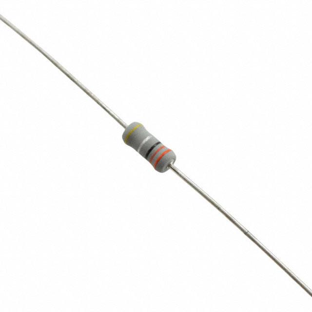
Marking
EMC resistors are colour coded with five bands. Four of the bands indicate value and tolerance in accordance with
IEC62. Parts with 20% tolerance have no fourth band. A fifth yellow band denotes constant voltage fusibility.
Performance Data
Maximum
Load at Rated Power: 1000hrs @ 70°C
ΔR%
5
Shelf life: 12 months at room temperature
ΔR%
2
Derating from rated power at 70°C
Zero at 155°C
ΔR%
Climatic
3
Climatic Category
50/155/56
Temperature rapid change
ΔR%
0.5
Resistance to solder heat
ΔR%
0.5
Pulse Performance
700
700
700
600
600
600
500
500
500
400
400
400
300
300
300
200
200
200
100
100
100
000
10 20
20 30 40 50 60 70
000 10
10 20 3030 4040 5050 6060 7070
Value(Ohms)
(Ohms)
Value
Value (Ohms)
Single
Rectangular
Pulse
Single
Rectangular
Pulse
Single
Rectangular
Pulse
10000
10000
10000
Pk Power (W)
Pk
PkPower
Power(W)
(W)
Pk
Pk Voltage
Voltage (V)
(V)
Pk Voltage (V)
IEC61000-4-5
IEC61000-4-5
1.2/50
Pulse
IEC61000-4-51.2/50
1.2/50s sPulse
1000
1000
1000
100
100
100
10
1010
1 11
0.01
0.1
0.01
0.01 0.10.1
EMC resistors fuse open circuit at overload powers
exceeding 60W within the time indicated on the Fusing
Characteristic. Their fusing performance at lower overload
powers is not specified.
Fusing Characteristic
(Constant Voltage)
Max. Fusing Time (s)
After fusing, the resistance is at least 100 times greater
than the original nominal value.
100
1000 10000
101010 100
100 1000
1000 10000
10000
Pulse Duration
(ms)
Pulse
PulseDuration
Duration(ms)
(ms)
Fusing Performance
EMC resistors fuse safely in the event of a 115Vrms /
240Vrms overload (line / mains short circuit condition)
without burning or emitting incandescent particles.
1 11
20
15
10
5
0
(4R7-8R2)
(10R-68R)
40
50
60
70
80
90
100
Initial Power (W)
General Note
TT Electronics reserves the right to make changes in product specification without notice or liability.
All information is subject to TT Electronics’ own data and is considered accurate at time of going to print.
BI Technologies IRC Welwyn
www.ttelectronics.com/resistors
© TT Electronics plc
11.20
�Application Notes
Application Notes
Pulse Withstanding
Fusible
1. If the resistors are to dissipate full rated power, it is recommended that the terminations should not be soldered closer than
4mm from the body.
Flameproof
Metal Film Resistors
(Delete redundant subtitle)
2. Due to operating temperature limits imposed by some PCB materials, derating may be necessary. An estimate of the
EMC Seriestemperature rise to be expected at the center of the body can be calculated using the thermal impedance figures given under
Electrical Data.
3. For the purpose of UL approval, the following points should be observed:
Application Notes
3.1 To protect against fire under all conditions of overload, a positive clearance of at least 13mm should be provided
between the body of the resistor and any combustible materials.
positive clearance
13mm should
be provided between
theterminations
resistor body should
or terminations
and uninsulated
1. If the resistors are3.2
toAdissipate
full ratedofpower,
it is recommended
that the
not be soldered
closerparts
thanof4mm from
opposite polarity or uninsulated dead metal parts.
the body.
3.3 Limited Short Circuit testing should be performed in the complete appliance.
2. Due to operating
temperature
imposed
some
PCB
materials,
derating
may be
necessary.
An estimate
of the
temperature
rise
4. ULW
resistors canlimits
also be
suppliedby
with
radial,
goalpost
or lancet
pre-formed
leads.
In particular
ULW2, ULW3,
ULW4
and
to be expected can
be
calculated
using
the
thermal
impedance
figures
given
under
Electrical
Data.
ULW5 are available in ZI-form SMD format packed in blister tape – see
http://www.ttelectronics.com/sites/default/files/resistors-datasheets/ZI-form.pdf
(This diagram exists on WP-S,
so just
it)
3. To protect against fire under all conditions of overload, a positive clearance of at least 13mm should
be copy
provided
between the body of
the resistor and any combustible materials.
4. EMC resistors can also be supplied loose packed with radial, goalpost or lancet pre-formed leads - see
https://www.ttelectronics.com/TTElectronics/media/ProductFiles/Resistors/ApplicationNotes/TN008-Resistors-Leadform-Capability.pdf,
or in ZI-form SMD format packed in blister tape - see
https://www.ttelectronics.com/TTElectronics/media/ProductFiles/Resistors/Datasheets/ZI-form.pdf
Also a 2W radial taped version is available as shown below
Dimension
EMC2R Radial
(mm) as shown below.
Also
a 2W radial Taped
taped Dimensions
version* is available
Notation Nominal
Tolerance
(mm)
Component BodyULWP2R
Length Radial Taped Dimensions
L
10.0 Max
Dimension
Component Body Diameter
Component Body Length
Terminal Lead Diameter
Component Body Diameter
Component PitchTerminal Lead Diameter
Pitch of Holes Component Pitch
Notation
Nominal
Tolerance
D
4.0 Max
L
10.0 Max
dD
0.8
Nom
4.0 Max
Pd
12.7
±0.5
0.8 Nom
PoP
12.7
±0.2
5
±0.5
Pitch of Holes
10
±0.2
P1Po
3.85
±0.3
Distance between Hole & Component
3.85
±0.3
Distance between Hole &
P2P1
5.85
±0.5
Component
5.85
±0.5
Lead Pitch
FP2
5.0
+0.75 -0.34
Lead Pitch
F
5.0
+0.75 -0.34
Width of Backing Strip
W
18.0
±0.3
Width of Backing Strip
W
18.0
±0.3
Position of Hole
W1
9.0
±0.25
Position of Hole
W1
9.0
±0.25
Diameter of Hole
Do
4.0
±0.3
Diameter of Hole
Do
4.0
±0.3
Height to Lead Form
HoHo
16.0
±0.3
Height to Lead Form
16.0
±0.3
Height from LeadHeight
Formfrom Lead Form
Ho1
21.7
Ho1
17.0Max
MAX
Height to ResistorHeight to Resistor
Ho2
18.0
Ho2
18.0Max
MIN
Width of Adhesive
Tape
W2
15.0
±0.5
Width
of Adhesive Tape
W2
15.0
±0.5
Length of protrusion
很抱歉,暂时无法提供与“EMC2-33RKI”相匹配的价格&库存,您可以联系我们找货
免费人工找货- 国内价格 香港价格
- 6000+1.215256000+0.15735