Miniature Low Profile
Shielded Surface Mount Inductors
HM66 Series
Features:
• Operating temperature range -40°C to +125°C
• Ambient temperature, maximum 80°C
• Temperature rise, maximum 40°C
• Operating frequency up to 3MHz
• RoHS compliant
All parts are Pb free and comply with EU RoHS Directive 2011/65/EU with amendment EU 2015/863 (RoHS 3)
Description:
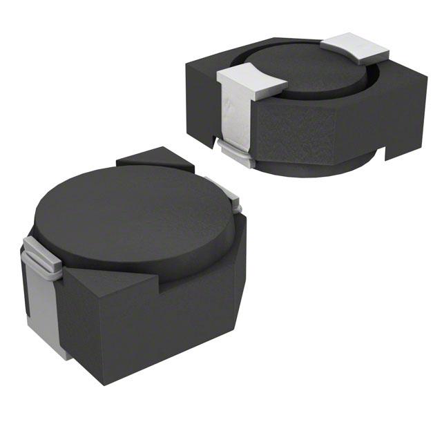
The HM66 is a miniature low profile shielded surface mount inductor. It is characterized by low losses at high frequencies.
These compact power inductors offer excellent current handling, low DC resistance and magnetic shielding for high-density
mounting. There are total 8 case sizes on this from 3.8x3.8mm 1.85mm max height up to 10.0x10.2mm 4.0mm max height.
Applications:
•
•
•
•
•
•
•
Low profile buck DC-DC converters
Low profile POL converters
Output power filter for forward converters
Power inductance for electronic breakers
Industrial automation systems
Industrial DC-DC converters
Industrial EMI filters
General Note
TT Electronics reserves the right to make changes in product specification without
notice or liability. All information is subject to TT Electronics’ own data and is
considered accurate at time of going to print.
© TT electronics plc
TT Electronics | BI Technologies
A-1445, Jalan Tanjung Api, 25050 Kuantan, Pahang Darul Makmur, Malaysia
Ph: +60 9 565 8888
https://www.ttelectronics.com/contact-us/
Issue 05
10/2022 Page 1
�Miniature Low Profile
Shielded Surface Mount Inductors
HM66 Series
Electrical Specifications
Inductance (1)
Nominal
μH ± 20 %
DC
Resistance
Ω Max.
Rated (2)
Current
Amps
Figure
HM66-151R5LFTR7
1.5
0.055
1.55
1
HM66-152R2LFTR7
2.2
0.072
1.20
1
HM66-153R3LFTR7
3.3
0.085
1.10
1
HM66-154R7LFTR7
4.7
0.105
0.90
1
HM66-156R8LFTR7
6.8
0.170
0.73
1
HM66-15100LFTR7
10
0.210
0.55
1
HM66-15150LFTR7
15
0.295
0.45
1
HM66-15220LFTR7
22
0.430
0.40
1
HM66-15330LFTR7
33
0.675
0.32
1
HM66-201R0LFTR13
1.0
0.045
1.72
1
HM66-202R2LFTR13
2.2
0.075
1.32
1
HM66-202R7LFTR13
2.7
0.105
1.28
1
HM66-203R3LFTR13
3.3
0.110
1.04
1
HM66-203R9LFTR13
3.9
0.155
0.88
1
HM66-204R7LFTR13
4.7
0.162
0.84
1
HM66-205R6LFTR13
5.6
0.170
0.80
1
HM66-206R8LFTR13
6.8
0.200
0.76
1
HM66-208R2LFTR13
8.2
0.245
0.68
1
HM66-20100LFTR13
10
0.200
0.61
1
HM66-20120LFTR13
12
0.210
0.56
1
HM66-20150LFTR13
15
0.240
0.50
1
HM66-20180LFTR13
18
0.338
0.48
1
HM66-20220LFTR13
22
0.397
0.41
1
HM66-20270LFTR13
27
0.441
0.35
1
HM66-20330LFTR13
33
0.694
0.32
1
HM66-20390LFTR13
39
0.709
0.30
1
HM66-301R2LFTR13
HM66-301R8LFTR13
HM66-302R2LFTR13
1.2
1.8
2.2
0.024
0.028
0.031
2.56
2.20
2.04
1
1
1
Part Number
General Note
TT Electronics reserves the right to make changes in product specification without
notice or liability. All information is subject to TT Electronics’ own data and is
considered accurate at time of going to print.
© TT electronics plc
TT Electronics | BI Technologies
A-1445, Jalan Tanjung Api, 25050 Kuantan, Pahang Darul Makmur, Malaysia
Ph: +60 9 565 8888
https://www.ttelectronics.com/contact-us/
Issue 05
10/2022 Page 2
�Miniature Low Profile
Shielded Surface Mount Inductors
HM66 Series
Electrical Specifications
Inductance (1)
Nominal
μH ± 20 %
DC
Resistance
Ω Max.
Rated (2)
Current
Amps
Figure
HM66-302R7LFTR13
2.7
0.043
1.60
1
HM66-303R3LFTR13
3.3
0.049
1.57
1
HM66-303R9LFTR13
3.9
0.065
1.44
1
HM66-304R7LFTR13
4.7
0.072
1.32
1
HM66-305R6LFTR13
5.6
0.101
1.17
1
HM66-306R8LFTR13
6.8
0.109
1.12
1
HM66-308R2LFTR13
8.2
0.118
1.04
1
HM66-30100LFTR13
10
0.128
1.00
1
HM66-30120LFTR13
12
0.132
0.84
1
HM66-30150LFTR13
15
0.149
0.76
1
HM66-30180LFTR13
18
0.166
0.72
1
HM66-30220LFTR13
22
0.235
0.70
1
HM66-30270LFTR13
27
0.261
0.58
1
HM66-30330LFTR13
33
0.378
0.56
1
HM66-30390LFTR13
39
0.384
0.50
1
HM66-30470LFTR13
47
0.587
0.48
1
HM66-30560LFTR13
56
0.625
0.41
1
HM66-30680LFTR13
68
0.699
0.35
1
HM66-30820LFTR13
82
0.915
0.32
1
HM66-30101LFTR13
100
1.020
0.29
1
HM66-30121LFTR13
120
1.270
0.27
1
HM66-30151LFTR13
150
1.350
0.24
1
HM66-30181LFTR13
180
1.540
0.22
1
HM66-404R1LFTR13
4.1
0.057
1.95
1
HM66-405R4LFTR13
5.4
0.076
1.60
1
HM66-406R2LFTR13
6.2
0.096
1.40
1
HM66-408R9LFTR13
8.9
0.116
1.25
1
HM66-40100LFTR13
10
0.124
1.20
1
HM66-40120LFTR13
12
0.153
1.10
1
Part Number
General Note
TT Electronics reserves the right to make changes in product specification without
notice or liability. All information is subject to TT Electronics’ own data and is
considered accurate at time of going to print.
© TT electronics plc
TT Electronics | BI Technologies
A-1445, Jalan Tanjung Api, 25050 Kuantan, Pahang Darul Makmur, Malaysia
Ph: +60 9 565 8888
https://www.ttelectronics.com/contact-us/
Issue 05
10/2022 Page 3
�Miniature Low Profile
Shielded Surface Mount Inductors
HM66 Series
Electrical Specifications
Inductance (1)
Nominal
μH ± 20 %
DC
Resistance
Ω Max.
Rated (2)
Current
Amps
Figure
HM66-40150LFTR13
15
0.196
0.97
1
HM66-40180LFTR13
18
0.210
0.85
1
HM66-40220LFTR13
22
0.290
0.80
1
HM66-40270LFTR13
27
0.330
0.75
1
HM66-40330LFTR13
33
0.386
0.65
1
HM66-40390LFTR13
39
0.520
0.57
1
HM66-40470LFTR13
47
0.595
0.54
1
HM66-40560LFTR13
56
0.665
0.50
1
HM66-40680LFTR13
68
0.840
0.43
1
HM66-40820LFTR13
82
0.978
0.41
1
HM66-40101LFTR13
100
1.200
0.36
1
HM66-502R5LFTR13
2.5
0.018
2.60
1
HM66-503R0LFTR13
3.0
0.024
2.40
1
HM66-504R2LFTR13
4.2
0.031
2.20
1
HM66-505R3LFTR13
5.3
0.038
1.90
1
HM66-506R2LFTR13
6.2
0.045
1.80
1
HM66-508R2LFTR13
8.2
0.053
1.60
1
HM66-50100LFTR13
10
0.065
1.30
1
HM66-50120LFTR13
12
0.076
1.20
1
HM66-50150LFTR13
15
0.103
1.10
1
HM66-50180LFTR13
18
0.110
1.00
1
HM66-50220LFTR13
22
0.122
0.90
1
HM66-50270LFTR13
27
0.175
0.85
1
HM66-50330LFTR13
33
0.189
0.75
1
HM66-50390LFTR13
39
0.212
0.70
1
HM66-50470LFTR13
47
0.260
0.62
1
HM66-50560LFTR13
56
0.305
0.58
1
HM66-50680LFTR13
68
0.355
0.52
1
HM66-50820LFTR13
82
0.463
0.46
1
Part Number
General Note
TT Electronics reserves the right to make changes in product specification without
notice or liability. All information is subject to TT Electronics’ own data and is
considered accurate at time of going to print.
© TT electronics plc
TT Electronics | BI Technologies
A-1445, Jalan Tanjung Api, 25050 Kuantan, Pahang Darul Makmur, Malaysia
Ph: +60 9 565 8888
https://www.ttelectronics.com/contact-us/
Issue 05
10/2022 Page 4
�Miniature Low Profile
Shielded Surface Mount Inductors
HM66 Series
Electrical Specifications
Inductance (1)
Nominal
μH ± 20 %
DC
Resistance
Ω Max.
Rated (2)
Current
Amps
Figure
HM66-50101LFTR13
100
0.520
0.42
1
HM66-603R0LFTR13
3.0
0.024
3.00
1
HM66-603R9LFTR13
3.9
0.027
2.60
1
HM66-605R0LFTR13
5.0
0.031
2.40
1
HM66-606R0LFTR13
6.0
0.035
2.25
1
HM66-607R3LFTR13
7.3
0.054
2.10
1
HM66-608R6LFTR13
8.6
0.058
1.85
1
HM66-60100LFTR13
10
0.065
1.70
1
HM66-60120LFTR13
12
0.070
1.55
1
HM66-60150LFTR13
15
0.084
1.40
1
HM66-60180LFTR13
18
0.095
1.32
1
HM66-60220LFTR13
HM66-60270LFTR13
HM66-60330LFTR13
22
27
33
0.128
0.142
0.165
1.20
1.05
0.97
1
1
1
HM66-60390LFTR13
39
0.210
0.86
1
HM66-60470LFTR13
47
0.238
0.80
1
HM66-60560LFTR13
56
0.277
0.73
1
HM66-60680LFTR13
68
0.304
0.65
1
HM66-60820LFTR13
82
0.390
0.60
1
HM66-60101LFTR13
100
0.535
0.54
1
HM66-703R3LFTR13
3.3
0.020
3.50
1
HM66-705R0LFTR13
5.0
0.024
2.90
1
HM66-706R2LFTR13
6.2
0.027
2.50
1
HM66-707R4LFTR13
7.4
0.031
2.30
1
HM66-708R7LFTR13
8.7
0.034
2.20
1
HM66-70100LFTR13
10
0.038
2.00
1
HM66-70120LFTR13
12
0.053
1.70
1
HM66-70150LFTR13
15
0.057
1.60
1
HM66-70180LFTR13
18
0.092
1.50
1
Part Number
General Note
TT Electronics reserves the right to make changes in product specification without
notice or liability. All information is subject to TT Electronics’ own data and is
considered accurate at time of going to print.
© TT electronics plc
TT Electronics | BI Technologies
A-1445, Jalan Tanjung Api, 25050 Kuantan, Pahang Darul Makmur, Malaysia
Ph: +60 9 565 8888
https://www.ttelectronics.com/contact-us/
Issue 05
10/2022 Page 5
�Miniature Low Profile
Shielded Surface Mount Inductors
HM66 Series
Electrical Specifications
Inductance (1)
Nominal
μH ± 20 %
DC
Resistance
Ω Max.
Rated (2)
Current
Amps
Figure
HM66-70220LFTR13
22
0.096
1.30
1
HM66-70270LFTR13
27
0.109
1.20
1
HM66-70330LFTR13
33
0.124
1.10
1
HM66-70390LFTR13
39
0.138
1.00
1
HM66-70470LFTR13
47
0.155
0.95
1
HM66-70560LFTR13
56
0.202
0.85
1
HM66-70680LFTR13
68
0.234
0.75
1
HM66-70820LFTR13
82
0.324
0.70
1
HM66-70101LFTR13
100
0.358
0.65
1
HM66-70221LFTR13
220
0.820
0.45
1
HM66-801R5LFTR13
1.5
0.0081
10.0
2
HM66-802R5LFTR13
2.5 ± 30%
0.0105
7.50
2
HM66-803R8LFTR13
3.8
0.017
6.00
2
HM66-805R2LFTR13
5.2
0.022
5.50
2
HM66-807R0LFTR13
7
0.027
4.80
2
HM66-80100LFTR13
10
0.035
4.40
2
HM66-80150LFTR13
15
0.050
3.60
2
HM66-80220LFTR13
22
0.073
2.90
2
HM66-80330LFTR13
33
0.093
2.30
2
HM66-80470LFTR13
47
0.128
2.10
2
HM66-80680LFTR13
68
0.213
1.50
2
HM66-80101LFTR13
100
0.304
1.35
2
HM66-80151LFTR13
150
0.506
1.15
2
HM66-80221LFTR13
220
0.756
0.92
2
HM66-80331LFTR13
330
1.090
0.70
2
HM66-80561LFTR13
560
1.900
0.45
2
HM66-80102LFTR13
1000
4.000
0.40
2
Part Number
Notes: (1) Test conditions for case sizes 15, 20, 30 , 80 = 100 kHz, 0.1 V without DC current. Test conditions for case sizes 40, 50, 60, 70 = 10 kHz, 0.1 V without DC current.
(2) Rated DC current is the approximate current at which inductance will be decreased by 35% from its initial (zero DC) value or the DC curent at which ΔT = 40°C,
whichever is lower.
General Note
TT Electronics reserves the right to make changes in product specification without
notice or liability. All information is subject to TT Electronics’ own data and is
considered accurate at time of going to print.
© TT electronics plc
TT Electronics | BI Technologies
A-1445, Jalan Tanjung Api, 25050 Kuantan, Pahang Darul Makmur, Malaysia
Ph: +60 9 565 8888
https://www.ttelectronics.com/contact-us/
Issue 05
10/2022 Page 6
�Miniature Low Profile
Shielded Surface Mount Inductors
HM66 Series
Electrical Schematic
Outline Dimensions
Case
Size
Figure
A
B
C Max
15
1
3.8 ± 0.5
3.8 ± 0.5
1.85
20
1
4.7 ± 0.5
4.7 ± 0.5
30
1
4.7 ± 0.5
40
1
50
D
G Max
H
I
J
3.8 ± 0.3 1.1 ± 0.15 3.8 ± 0.3
5.5
1.1
4.5
1.7
2.1
4.5 ± 0.3 1.5 ± 0.15 4.5 ± 0.3
6.9
1.5
5.3
1.9
4.7 ± 0.5
3.0
4.5 ± 0.3 1.5 ± 0.15 4.5 ± 0.3
6.9
1.5
5.3
1.9
5.7± 0.5
5.7± 0.5
2.0
5.5± 0.3 2.0 ± 0.15 5.5± 0.3
8.2
2.0
6.3
2.15
1
5.7 ± 0.5
5.7 ± 0.5
3.0
5.5± 0.3
2.1 ± 0.1
5.5± 0.3
8.2
2.0
6.3
2.15
60
1
6.7 ± 0.5
6.7 ± 0.5
3.0
6.5± 0.3
2.1 ± 0.1
6.5± 0.3
9.5
2.0
7.3
2.65
70
1
6.7 ± 0.5
6.7 ± 0.5
4.0
6.5± 0.3
2.1 ± 0.1
6.5± 0.3
9.5
2.0
7.3
2.65
80
2
10.0± 0.5 10.2± 0.5
4.0
3.0 ± 0.1
7.7 ± 0.3 1.2± 0.15
-
7.3
3.2
1.7
General Note
TT Electronics reserves the right to make changes in product specification without
notice or liability. All information is subject to TT Electronics’ own data and is
considered accurate at time of going to print.
© TT electronics plc
E
F
TT Electronics | BI Technologies
A-1445, Jalan Tanjung Api, 25050 Kuantan, Pahang Darul Makmur, Malaysia
Ph: +60 9 565 8888
https://www.ttelectronics.com/contact-us/
Issue 05
10/2022 Page 7
�Miniature Low Profile
Shielded Surface Mount Inductors
HM66 Series
Packaging
Embossed Tape and Reel
Diameter:
Standard:
Reel:
Capacity:
Case size 15
All other case sizes
=
=
7 ’’ (177.8mm)
13’’ (330.2mm)
Case size 20
Case size 30,40,50
Case size 60
Case size 15,70
Case size 80
=
=
=
=
=
3,000 Units
2,000 Units
1,500 Units
1,000 Units
800 Units
Ordering Information
HM66 – XX 100 LF TR13
Model Series
Case Size
80 = Figure 2
15, 20, 30, 40, 50, 60, 70 = Figure 1
Tape & Reel Packing
7 – 7 ” reel
13 - 13 ” reel
Lead-Free
Inductance code:
First 2 digits are significant. Last digit denotes
the number of trailing zeros. For values below
10μH, ” R” denotes the decimal point.
General Note
TT Electronics reserves the right to make changes in product specification without
notice or liability. All information is subject to TT Electronics’ own data and is
considered accurate at time of going to print.
© TT electronics plc
TT Electronics | BI Technologies
A-1445, Jalan Tanjung Api, 25050 Kuantan, Pahang Darul Makmur, Malaysia
Ph: +60 9 565 8888
https://www.ttelectronics.com/contact-us/
Issue 05
10/2022 Page 8
�Cautions & Warnings
1.
All components are manufactured, designed, and promoted for application in general electronics devices. For specific
application use such as in automotive, medical, military and aerospace industry other than for general electronic
devices, BI Technologies must be asked for written approval before incorporating the components into those areas.
2.
Any components that will be used in high-reliability / high level of safety applications should be pre-evaluated by the
end customer especially in customer applications in which the malfunction or failure of an electronic component could
endanger human life or health.
3.
The customer shall be responsible for evaluating and confirming BI Technologies product is suitable for use in
customer's applications. If customer applications requiring a very high level of operational safety and especially in
customer applications in which a failure of an electronic component could endanger human life or health, it must
therefore be ensured by means of suitable design of the customer application or other action taken by the customer
such that no injury or damage is sustained by third parties in the event of malfunction or failure of an electronic
component.
4.
Customer must be cautioned to verify that data sheets are the updated ones before placing orders especially of
standard series.
5.
Customer need to use the part within warranty period as stated in quotation. Any trouble or failure of electronic
components happening during their long life span which cannot be eliminated even after following the instruction
within existing technology, BI Technologies would not be liable for it.
6.
Many coating/potting materials would shrink as they harden. They therefore applies a pressure on the plastic housing
or core. This pressure can have an effect on electrical properties and in extreme cases can damage the core or plastic
housing mechanically. It is necessary to check whether the coating/potting material used may attacks or destroys the
wire insulation, plastics or glue. The effect of the coating/potting material can change the high-frequency behavior of
the components. Many coating/potting materials have a negative effect (chemically and mechanically) on the winding
wires, insulation materials and connecting points. Customers are always obligated to determine whether and to what
extent their coating materials influence the component. Customers are responsible and bear all risk for the use of the
coating material. BI Technologies does not assume any liability for failures of our components that are caused by the
coating material.
7.
Washing / Cleaning process may jeopardize the product and cause a defect. Washing agents may harm the long-term
functionality of the product. The customer shall be responsible for evaluating and confirming the product is suitable for
use in customer's applications upon washing/cleaning process as its customer process application related.
8.
Products should not be kept in unsuitable storage conditions, such as areas susceptible to high humidity, high
temperatures, dust or corrosion where for example atmospheres should be free of chlorine and sulfur bearing
compounds. Recommended storage condition in general is +10°C … +40 °C, humidity ≤75% RH. Temperature
fluctuations should be minimized to avoid condensation on the parts. Avoid storage near strong magnetic fields, as this
might magnetize the product.
9.
The storage period should not be longer than 12 months (In the specific storage environment). Oxidization may occur
on the terminals. Hence all products shall be consumed within 12 months after the shipping date. If the time is more
than 12 months, please check the solderability before use it.
10. Don't touch electrodes terminals directly with bare hands as oil stains may inhibit proper soldering. Always ensure
optimum conditions for soldering.
11. Terminals should not be bend or subjected to excessive stress. If the terminals are cable harness type, do not use cable
harness to carry the unit or pull the cable harness with a force. It may cause failure on unit immediately or latent effect.
12. Avoid placing magnetic components near the edge of the PCB. It is in customer discretion to have proper design and
PCB layout such that component are not damaged in any way of handling nor causing any EMI issue.
General Note
TT Electronics reserves the right to make changes in product specification without
notice or liability. All information is subject to TT Electronics’ own data and is
considered accurate at time of going to print.
© TT electronics plc
TT Electronics | BI Technologies
A-1445, Jalan Tanjung Api, 25050 Kuantan, Pahang Darul Makmur, Malaysia
Ph: +60 9 565 8888
https://www.ttelectronics.com/contact-us/
Issue 05
10/2022 Page 9
�Cautions & Warnings
13. Don't touch any exposed winding part and avoid coming into contact with the guide of the electrode as due to charge
stored it may cause an electric shock. It is customer discretion to inform all relevant personal handling the components
accordingly.
14. The inductor / coil / common mode choke generates heat when current is applied. Please take consideration on this
during the design or testing stage.
15. Ferrites are sensitive to direct impact. This can cause the core material to flake, or lead to breakage of the core. Always
handle the product with care to prevent any damage.
16. Our specification specifies the quality of the component as a single unit. Please ensure the component is thoroughly
evaluated in customer application circuit, therefor even for customized products, conclusive validation of the
component in the circuit can only be carried out by customer.
17. The general testing condition is in the room temperature 25°C +/- 5°C and humidity under 70% RH, which is applied to
all products. It is the customer's responsibility to validate that a particular product with the properties described in the
product specification is suitable for use in a particular application. Parameters provided in datasheets and / or
specifications may vary in different applications and performance may vary over time. All operating parameters,
including typical parameters, must be validated for each customer application by the customer.
18. If have any query, please feel free to contact our sales team.
General Note
TT Electronics reserves the right to make changes in product specification without
notice or liability. All information is subject to TT Electronics’ own data and is
considered accurate at time of going to print.
© TT electronics plc
TT Electronics | BI Technologies
A-1445, Jalan Tanjung Api, 25050 Kuantan, Pahang Darul Makmur, Malaysia
Ph: +60 9 565 8888
https://www.ttelectronics.com/contact-us/
Issue 05
10/2022 Page 10
�