Silicon Phototransistor
OP570 Series
OP570
Features:
x�
x�
x�
x�
x�
SMD plastic package
High photo sensitivity
Fast response time
Choice of four lead configurations
IR transmissive plastic package
OP573
OP571
OP572
Description:
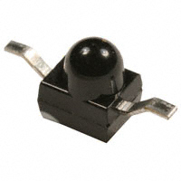
Each device in this series is an NPN silicon phototransistor mounted in an opaque plastic SMD package, with an
integral molded lens that enables a narrow acceptance angle and a higher collector current than devices without a
lense.
The OP570 series has four lead configurations and is compatible with most automated mounting equipment. The
OP570 series is mechanically and spectrally matched to the OP270 series infrared LEDs.
Please refer to Application Bulletins 208 and 210 for additional design information and reliability (degradation) data.
Applications:
Ordering Information
x� Non-contact position sensing
x� Datum detection
x� Machine automation
x� Optical encoders
x� IrDA
x� Reflective and transmissive sensors
Part Number
OP570
OP571
OP572
OP573
Sensor
Phototransistor
Viewing
Angle
Lead
Length
25°
Axial
Gull Wing
Yoke
Rev. Gull
OP570
OP571
OP571
OP572
1
OP573
Pin # Transistor
1
Collector
2
Emitter
2
RoHS
OPTEK reserves the right to make changes at any time in order to improve design and to supply the best product possible.
OPTEK Technology Inc.— 1645 Wallace Drive, Carrollton, Texas 75006
Phone: (800) 341-4747 FAX: (972) 323– 2396 sensors@optekinc.com www.optekinc.com
Issue 1.3 10/07
Page 1 of 4
�Silicon Phototransistor
OP570 Series
OP573
DIMENSIONS ARE IN:
OP570
[MILLIMETERS]
INCHES
TOLERANCE IS ± .0039 [0.1]
OP571
OP572
2
1
Pin #
Transistor
1
Collector
2
Emitter
OPTEK reserves the right to make changes at any time in order to improve design and to supply the best product possible.
Issue 1.3
10/07
Page 2 of 4
OPTEK Technology Inc. — 1645 Wallace Drive, Carrollton, Texas 75006
Phone: (972) 323-2200 or (800) 341-4747
FAX: (972) 323-2396 sensors@optekinc.com www.optekinc.com
�Silicon Phototransistor
OP570 Series
Absolute Maximum Ratings (TA=25°C unless otherwise noted)
Storage Temperature Range
-40o C to +85o C
Operating Temperature Range
-25o C to +85o C
Collector-Emitter Voltage
30 V
Emitter-Collector Voltage
5V
Collector Current
20 mA
260° C(1)
Lead Soldering Temperature [1/16 inch (1.6 mm) from case for 5 seconds with soldering iron]
130 mW (2)
Power Dissipation
Notes:
1. Solder time less than 5 seconds at temperature extreme.
2. Derate linearly at 2.17 mW/° C above 25° C.
Electrical Characteristics (TA = 25rC unless otherwise noted)
SYMBOL
PARAMETER
MIN
TYP
MAX
UNITS
2.5
-
-
mA
TEST CONDITIONS
Input Diode
IC (ON)
On-State Collector Current
VCE = 5.0 V, EE = 5.0 mW/cm2
(1)
VCE(SAT)
Forward Voltage
-
-
0.4
V
IC = 100 µA, EE = 2.0 mW/cm2 (1)
ICEO
Reverse Current
-
-
100
nA
VCE = 5.0 V, EE = 0(2)
VBR(CEO)
Wavelength at Peak Emission
30
-
-
V
IC = 100 µA
V(BR)ECO
Emission Angle at Half Power Points
5
-
-
V
IE = 100 µA
Notes:
1. Light source is an unfiltered GaAl LED with a peak emission wavelength of 935nm and a radiometric intensity level which varies less
than 10% over the entire lens surface of the phototransistor being tested.
(0.04 Ta-3.4)
2. To calculate typical collector dark current in µA, use the formula ICEO = 10
where Ta is the ambient temperature in ° C.
Relative Collector Current
140%
Relative On-State Collector Current vs. Temperature
140%
Normalized at Ee = 5mW/cm2
Conditions: VCE = 5V,
= 935nm, TA = 25 °C
130%
Relative Collector Current
160%
Relative On-State Collector
Current vs. Irradiance
120%
100%
80%
60%
40%
20%
0
Normalized at TA = 25°C .
Conditions: VCE = 5V,
= 935nm, TA = 25 °C
120%
110%
100%
90%
80%
70%
1.0
2.0
3.0
4.0
5.0
6.0
Ee—Irradiance (mW/cm2)
7.0
8.0
-25
0
25
50
75
100
Temperature—(°C)
OPTEK reserves the right to make changes at any time in order to improve design and to supply the best product possible.
OPTEK Technology Inc. — 1645 Wallace Drive, Carrollton, Texas 75006
Phone: (972) 323-2200 or (800) 341-4747
FAX: (972) 323-2396 sensors@optekinc.com www.optekinc.com
Issue 1.3 10/07
Page 3 of 4
�Silicon Phototransistor
OP570 Series
Relative Collector Current
vs. Ambient Termperature
Collector Current vs.
Collector-Emitter Voltage
Collector Dark Current
Vs. Ambient Temperature
Spectral Sensitivity
vs. Wavelength
Normalized Spectral Intensity
1.0
0.8
0.6
0.4
0.2
600
700
800
900
1000
1100
1200
Wavelength — O�(nm)
OPTEK reserves the right to make changes at any time in order to improve design and to supply the best product possible.
Issue 1.3
10/07
Page 4 of 4
OPTEK Technology Inc. — 1645 Wallace Drive, Carrollton, Texas 75006
Phone: (972) 323-2200 or (800) 341-4747
FAX: (972) 323-2396 sensors@optekinc.com www.optekinc.com
�
很抱歉,暂时无法提供与“OP573”相匹配的价格&库存,您可以联系我们找货
免费人工找货- 国内价格 香港价格
- 3000+1.649013000+0.21375
- 5000+1.578225000+0.20457
- 7000+1.536957000+0.19922
- 10000+1.4973410000+0.19409
- 25000+1.4123025000+0.18306
- 50000+1.3612850000+0.17645