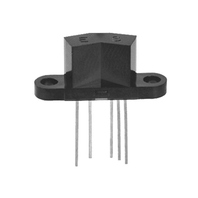
Photologic® Reflective Object Sensor
OPB760, OPB761, OPB762, OPB763 (Series N and T)
OPB770, OPB771, OPB772, OPB773 (Series NZ and TZ)
OPB760N
Features:
•
•
•
•
Choice of mounting configurations
Choice of four output configurations
.040” (10.160 mm) PCBoard mount (N and T series)
12” (304.800 mm) AWG 26 wires (NZ and TZ series)
OPB773TZ
Description:
The OPB760N, OPB760T, OPB770N and OPB770T series of reflective assemblies feature Photologic® output. The electrical
output can be specified as either TTL Totem-Pole or TTL Open-Collector, either of which can be supplied with inverter or
buffer output polarity.
OPB760N and OPB760T series devices are designed for PCBoard mounting and have 0.04” (10 mm) long leads.
OPB760T and OPB770T series devices are designed for remote mounting with two mounting tabs.
OPB770NZ and OPB770TZ series devices have 12” (305 mm) long, UL approved 26 AWG wires.
All devices in this series offer the added stability of a built-in hysteresis amplifier.
Custom electrical, wire and cabling and connectors are available. Contact your local representative or OPTEK for more
information.
Applications:
•
•
•
•
•
•
Non-contact Photologic®
reflective object sensor
Assembly line automation
Machine automation
Machine safety
End of travel sensor
Door sensor
Ordering Information
Part
LED Peak
Sensor
Reflection Distance
Mounting
Number Wavelength
Photologic®
(Inch) Min / Max
OPB760N
Totem-Pole
OPB761N
Open Collector
OPB762N
Inv-Totem-Pole
OPB763N
Inv-Open Collector
PCBoard .40”
(10.160 mm) leads)
OPB760T
Totem-Pole
OPB761T
Open Collector
OPB762T
Inv-Totem-Pole
OPB763T
Inv-Open Collector
890 nm
0.080" / 0.220”
OPB770NZ
Totem-Pole
OPB771NZ
Open Collector
OPB772NZ
Inv-Totem-Pole
OPB773NZ
Inv-Open Collector
12” (304.800 mm)
26 AWG wire
OPB770TZ
Totem-Pole
OPB771TZ
Open Collector
OPB772TZ
Inv-Totem-Pole
OPB773TZ
Inv-Open Collector
RoHS
General Note
TT Electronics reserves the right to make changes in product specification without
notice or liability. All information is subject to TT Electronics’ own data and is
considered accurate at time of going to print.
© TT electronics plc
TT Electronics | OPTEK Technology
2900 E. Plano Pkwy, Plano, TX 75074 | Ph: +1 972 323 2200
www.ttelectronics.com | sensors@ttelectronics.com
Issue D
02/2019
Page 1
�Photologic® Reflective Object Sensor
OPB760, OPB761, OPB762, OPB763 (Series N and T)
OPB770, OPB771, OPB772, OPB773 (Series NZ and TZ)
Electrical Specifications
OPB760, OPB770 Buffered Totem-Pole
OPB761, OPB771 Buffered Open Collector
VCC
VCC
OUT
OUT
GND
OPB762, OPB772 Inverted Totem-Pole
GND
OPB763, OPB773 Inverted Open-Collector
VCC
VCC
OUT
OUT
GND
General Note
TT Electronics reserves the right to make changes in product specification without
notice or liability. All information is subject to TT Electronics’ own data and is
considered accurate at time of going to print.
© TT electronics plc
GND
TT Electronics | OPTEK Technology
2900 E. Plano Pkwy, Plano, TX 75074 | Ph: +1 972 323 2200
www.ttelectronics.com | sensors@ttelectronics.com
Issue D
02/2019
Page 2
�Photologic® Reflective Object Sensor
OPB760, OPB761, OPB762, OPB763 (Series N and T)
OPB770, OPB771, OPB772, OPB773 (Series NZ and TZ)
Electrical Specifications
OPB760 (N and T Series)
OPB770 (NZ and TZ Series)
DIMENSIONS ARE IN:
X = 0.08” [2.0mm] to 0.22” [5.6mm]
[ MILLIMETERS]
INCHES
Pin #
Description
Pin#
Description
Color/Pin#
Description
Color/Pin#
Description
1
Cathode
3
Ground
Red-4
Anode
White-1
VCC
2
Anode
4
Output
Black-5
Cathode
5
VCC
General Note
TT Electronics reserves the right to make changes in product specification without
notice or liability. All information is subject to TT Electronics’ own data and is
considered accurate at time of going to print.
© TT electronics plc
Blue-2
Output
Green-3
Ground
TT Electronics | OPTEK Technology
2900 E. Plano Pkwy, Plano, TX 75074 | Ph: +1 972 323 2200
www.ttelectronics.com | sensors@ttelectronics.com
Issue D
02/2019
Page 3
�Photologic® Reflective Object Sensor
OPB760, OPB761, OPB762, OPB763 (Series N and T)
OPB770, OPB771, OPB772, OPB773 (Series NZ and TZ)
Electrical Specifications
Absolute Maximum Ratings (TA=25°C unless otherwise noted)
Supply Voltage, VCC (not to exceed 3 seconds)
10 V
Storage Temperature Range
-40° C to +85° C
Operating Temperature Range
-40° C to +70° C
Lead Soldering Temperature (1/16” inch (1.6 mm) from case for 5 seconds with soldering iron)
Input Diode Power Dissipation
(1)
260° C
(2)
100 mW
Output Photologic® Power Dissipation(3)
Total Device Power Dissipation
200 mW
(4)
300 mW
Voltage at Output Lead (Open Collector Output)
35 V
Diode Forward DC Current
40 mA
Diode Reverse DC Voltage
3V
Electrical Characteristics (TA = 25°C unless otherwise noted)
SYMBOL
PARAMETER
MIN
TYP
MAX
UNITS
TEST CONDITIONS
Input Diode
VF
Forward Voltage
-
-
1.8
V
IF = 40 mA, TA = 25° C
IR
Reverse Current
-
-
100
μA
VR = 2.0 V, TA = 25° C
4.75
-
5.25
V
Output Photologic® Sensor
VCC
Operating DC Supply Voltage
ICCL
Low Level Supply Current:
Buffered Totem-Pole Output(5)(6)
Buffered Open-Collector Output(5)(6)
-
-
10
10
mA
mA
Inverted Totem-Pole Output(5)
Inverted Open-Collector Output(5)
-
-
10
10
mA
mA
Vcc = 5.25 V, If = 25 mA (output open)
High Level Supply Current:
Buffered Totem-Pole Output(5)(6)
Buffered Open-Collector Output(5)
-
-
10
10
mA
mA
Vcc = 5.25 V, If = 25 mA (output open)
Inverted Totem-Pole Output(5)(6)
Inverted Open-Collector Output(5)(6)
-
-
10
10
mA
mA
Vcc = 5.25 V, If = 0 mA (output open)
High Level Output Current:
Buffered Open-Collector Output
-
-
100
100
µA
µA
Vcc = 4.5 V, If = 25 mA, VOH = 30 V, TA=25°C
Inverted Open-Collector Output
-
-
100
µA
Vcc = 4.5 V, If = 0 mA, VOH = 30 V, TA = 25°C
ICCH
IOH
Notes:
(1)
(2)
(3)
(4)
(5)
(6)
(7)
Vcc = 5.25 V, If = 0 mA (output open)
RMA flux is recommended. Duration can be extended to 10 seconds maximum when flow soldering.
Derate linearly 2.22 mW/°C above 25° C.
Derate linearly 4.44 mW/°C above 25° C.
Derate linearly 6.66 mW/°C above 25° C.Normal application would be with light source blocked, simulated by I F=0 mA.
Tested at d = 0.080” (mm) from a 90% diffuse white test surface.
Normal application would be with light source blocked, simulated by I F = 0 mA.
All parameters tested using pulse technique.
General Note
TT Electronics reserves the right to make changes in product specification without
notice or liability. All information is subject to TT Electronics’ own data and is
considered accurate at time of going to print.
© TT electronics plc
TT Electronics | OPTEK Technology
2900 E. Plano Pkwy, Plano, TX 75074 | Ph: +1 972 323 2200
www.ttelectronics.com | sensors@ttelectronics.com
Issue D
02/2019
Page 4
�Photologic® Reflective Object Sensor
OPB760, OPB761, OPB762, OPB763 (Series N and T)
OPB770, OPB771, OPB772, OPB773 (Series NZ and TZ)
Electrical Specifications
Electrical Characteristics (TA = 25°C unless otherwise noted)
SYMBOL
PARAMETER
MIN
TYP
MAX
UNITS
TEST CONDITIONS
-
-
25
mA
Hysteresis
1.1
-
2.0
-
Short Circuit Output Current:
Buffered Totem-Pole Output(1)
-15
-
-100
mA
Inverted Totem-Pole Output(1)
-15
-
-100
mA
Low Level Output Voltage:
Buffered Totem-Pole Output(1)(4)
Buffered Open-Collector Output(1)(4)
-
-
0.4
0.4
V
V
VCC = 4.5 V, IOL = 12.8 mA, IF = 0 mA or IF =
30 mA
Inverted Totem-Pole Output
Inverted Open-Collector Output(1)(4)
-
-
0.4
0.4
V
V
VCC = 4.5 V, IOL = 12.8 mA, IF = 25 mA
High Level Output Voltage:
Buffered Totem-Pole Output(1)
2.4
-
-
V
Inverted Totem-Pole Output(1)(4)
2.4
-
-
V
VCC = 4.5 V, IOH = -800 µA, IF = 0 mA
2.4
2.4
-
-
V
V
VCC = 4.5 V, IOH = -800 µA, IF = 30 mA
Output Photologic® Sensor (continued)
IF(+)
IF(+)/IF(-)
IOS
VOL
VOH
LED Positive-Going Threshold Current(2)
(2)
(3)
Inverted Totem-Pole Output
Inverted Open-Collector Output(3)
Vcc = 5 V, TA = 25° C
Vcc = 5 V
If = 25 mA, Vcc = 5.25 V, Output = GRD
If = 0 mA, Vcc = 5.25 V, Output = GRD
VCC = 4.5 V, IOH = -800 µA, IF = 25 mA
Notes:
(1) Tested at d = 0.080” (mm) from a 90% diffuse white test surface.
(2) Tested at d = 0.080” (mm), 0.150” (mm) and 0.220” (mm) from a 90% diffuse white test surface. Reference: Eastman Kodak,
Catalog #E 152 7795.
(3) Tested at d = 0.080” (mm), 0.150” (mm) and 0.220” (mm) from a 5% diffuse black test surface.
(4) Normal application would be with light source blocked, simulated by IF=0 mA.
(5) OPB760N through OPB763N series devices are terminated with 0.20” (mm) square leads designed for printed PCBoard
mounting.
(6) OPB770NZ through OPB773NZ series devices are terminated with 12 inches (mm) of 7-strand 26 AWG UL1429 insulated wire on
each terminal. A standard AMP No. 640442-5 connector has been attached to the lead wires to ease connection to wire
harnesses.
(7) OPB760T through OPB763T series devices are terminated with 0.020” (mm) square leads designed for printed PCBoard
mounting.
(8) OPB770TZ through OPB773TZ series are terminated with 12” (mm) of 7-strand 26 AWG UL1429 insulated wire on each terminal.
A standard AMP No. 640442-5 connector has been attached to the lead wires to ease connection to wire harnesses.
(9) All parameters tested using pulse technique.
General Note
TT Electronics reserves the right to make changes in product specification without
notice or liability. All information is subject to TT Electronics’ own data and is
considered accurate at time of going to print.
© TT electronics plc
TT Electronics | OPTEK Technology
2900 E. Plano Pkwy, Plano, TX 75074 | Ph: +1 972 323 2200
www.ttelectronics.com | sensors@ttelectronics.com
Issue D
02/2019
Page 5
�Photologic® Reflective Object Sensor
OPB760, OPB761, OPB762, OPB763 (Series N and T)
OPB770, OPB771, OPB772, OPB773 (Series NZ and TZ)
Performance
Logic Level vs Distance
1
1
1
1
1
Kodak 90% - Towards
Logic
Logic
Logic Level vs Distance
1
1
Copy Paper - Towards
1
Kodak 90% - Away
Copy Paper - Away
0
0
0
0
0
0
0.0
0.1
0.2
0.3
0.4
0.5
0.6
0.0
0.1
0.2
Distance (inches)
0.3
0.4
0.5
0.6
0.5
0.6
Distance (inches)
Logic Level vs Distance
Logic Level vs Distance
1
1
1
1
1
1
Logic
Logic
Kodak 19% - Towards
1
1
Avery Labels - Towards
Kodak 19% - Away
0
0
Avery Labels - Away
0
0
0
0
0.0
0.1
0.2
0.3
0.4
0.5
Distance (inches)
General Note
TT Electronics reserves the right to make changes in product specification without
notice or liability. All information is subject to TT Electronics’ own data and is
considered accurate at time of going to print.
© TT electronics plc
0.6
0.0
0.1
0.2
0.3
0.4
Distance (inches)
TT Electronics | OPTEK Technology
2900 E. Plano Pkwy, Plano, TX 75074 | Ph: +1 972 323 2200
www.ttelectronics.com | sensors@ttelectronics.com
Issue D
02/2019
Page 6
�Photologic® Reflective Object Sensor
OPB760, OPB761, OPB762, OPB763 (Series N and T)
OPB770, OPB771, OPB772, OPB773 (Series NZ and TZ)
Performance
Typical Trigger Current and Hysteresis Ratio
vs Ambient Temperature
Logic Level vs Distance
1
14
IF (+), IF(-) and IF(+)/IF(-) - Trigger Current and
Hysteresis Ratio
IF(+) mA
1
Logic
1
Retro 3M 3870 - Towards
1
0
Retro 3M 3870 - Away
0
IF(-) mA
12
Hys
10
8
6
4
2
0
0
0.0
0.1
0.2
0.3
0.4
0.5
-40 -30 -20 -10
0.6
Distance (inches)
10
20
30
40
50
60
70
80
Supply Current vs Ambient Temperature
Output Voltage vs Ambient Temperature
18
9
16
8
14
7
12
6
Typical Icc (mA)
Typical Output Voltage (V)
0
Ta - Ambient Temperature (°C)
10
8
5
4
3
6
4
2
Voh (V)
Vol (V)
2
Icch(mA)
Iccl(mA)
1
0
0
-40
-20
0
20
40
60
Ta -Ambient Temperature - (°C)
General Note
TT Electronics reserves the right to make changes in product specification without
notice or liability. All information is subject to TT Electronics’ own data and is
considered accurate at time of going to print.
© TT electronics plc
80
-40
-20
0
20
40
60
80
Ta -Ambient Temperature - (°C)
TT Electronics | OPTEK Technology
2900 E. Plano Pkwy, Plano, TX 75074 | Ph: +1 972 323 2200
www.ttelectronics.com | sensors@ttelectronics.com
Issue D
02/2019
Page 7
�