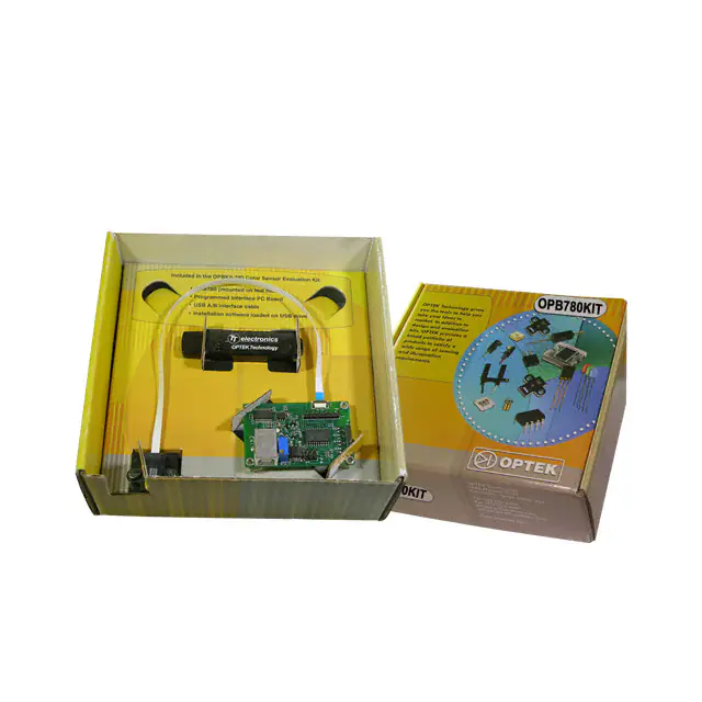
OPB780-Kit
Color Sensor Evaluation Kit
• The OPB780-Kit is designed to provide the design engineer an
easy way to evaluate the capability of the OPB780 Color Sensor.
The OPB780Z is a full color sensor with 4
different frequencies relating directly to a
specific color seen by the sensor.
Block
Current-to-Frequency
Out
Converter
The OPB780Z color sensor uses a
Photodiode Array
Light
programmable
light-to-frequency
S2
S3
converter that combines 64 configurable
silicon photodiodes (on a 144 um center
array and measuring 120 um x 120 um
6
4
each) and a current-to-frequency
converter on a single monolithic CMOS integrated
circuit, packaged in a small, lightweight package that
makes it ideal for using in miniature applications.
The output is a square wave (50% duty cycle) with a
frequency directly proportional to light chromaticity and
irradiance from four filtered diode arrays.
The light-to-frequency converter reads an 8 x 8 array of
photodiodes that consists of four groups of 16
photodiodes each, segregated by color:
16
photodiodes with red filters, 16 photodiodes with green
filters, 16 photodiodes with blue filters and 16
photodiodes with clear filters. Each color’s group of 16
photodiodes is interdigitated to minimize the effect of
non-uniformity of incident irradiance. Each color’s
group is also connected in parallel. The type of
photodiode used during operation is pin-selectable.
The internal photodiode used by the device is controlled
by two logic inputs, S2 and S3.
Pin 4 (S2)
Pin 6 (S3)
Diode Filter
H
H
Green
H
L
Clear
L
L
Red
L
H
Blue
7,8
SO
S3
S1
S2
4
OE
Out
3
Gnd
VDD
1,2
3
6
Cap (0.1µf)
5
LED
Pin Name
Pin #
Description
VDD
1, 2
Supply voltage
OUT
3
Output Frequency (FO)
S2
4
Photodiode type selection input
LED Anode
5
LED input
S3
6
Photodiode type selection input
GND/OE
7, 8
Sensor & LED Ground
DO NOT LOOK DIRECTLY AT LED
WITH UNSHIELDED EYES OR
DAMAGE TO RETINA MAY OCCUR.
The OPB780Z includes 10” [25.4cm] a Flat Flexible
interface Cable. Custom lengths of the cable can be
ordered either from OPTEK or most Flat Flexible Cable
(FFC) manufactures. The FFC is designed to interface
with an any standard 0.5mm spacing FFC connector
similar to the AVX ELCO connector.
(part number 04 6249 0080 00 800+).
The output of the device is designed to drive a standard
TTL or CMOS logic input over short distances.
OPTEK reserves the right to make changes at any time in order to improve design and to supply the best product possible.
OPTEK Technology Inc. — 1645 Wallace Drive, Carrollton, Texas 75006
Phone: (972) 323-2200 or (800) 341-4747
FAX: (972) 323-2396 sensors@optekinc.com www.optekinc.com
Issue A.2
11/09
Page 1 of 9
�OPB780-Kit
Color Sensor Evaluation Kit
All 16 photodiodes that have the same color filter are
connected in parallel. Package pin numbers 4 (S2)
and 6 (S3) can be used to select the desired
photodiode/filter configuration to optimize color
identification. All 64 photodiodes are 120µm x 120µm
in size and are on 144µm centers.
The output frequency provided by the OPB780Z may
vary from part to part and should be calibrated as
required to meet each application. The more colors
that are to be identified require more accurate
calibration and longer sampling rate. A small amount
of jitter will be present in the frequency provided for a
color and must be taken into consideration depending
on the accuracy required.
The OPB780Z photodiodes as provided are designed
to recognize ultraviolet, visible as well as near infrared
wavelengths (from 300 to 1,050 nanometers) The
graphs below show the typical Spectral Response for
each photodiode configuration. When a near infrared
rejecting filter similar to the Hoya CM500 is placed in
front of the sensor, the higher wavelengths (above 700
nm) are eliminated thus enhancing recognition of
colors in the visible range.
Typical Spectral Response
Full Wavelength Sensitivity
1.0
Relative Responsivity
The OPB780Z consist of:
1. White LED for illumination of the target
2. Photodiode Array consisting of:
16 Green Filter Diodes
16 Clear Filter Diodes
16 Red Filter Diodes
16 Blue Filter Diodes
3. Current to Frequency Converter
4. TTL and CMOS Drive Circuitry
5. Plastic Package with 10: (25.4cm) FFC
No rmalized to
Clear @ 680 nm
0.9
0.8
0.7
TA = 25° C
0.6
0.5
0.4
0.3
0.2
0.1
0.0
300
500
700
900
1100
λp Wavelength (nm)
Frequency-A
Frequency-B
The internal scaling is preconfigured for the highest
frequency output of typically 600kHz. The 600kHz
frequency shortens the sampling time providing a
small amount of jitter in the output frequency.
The user must take into consideration the luminance
intensity (amount of light) that may be acknowledged
by the human eye.
As the luminance intensity
decreases, the amount of color recognized is
diminished. In order to consistently reproduce a
specific color with the same output frequency, the
luminance intensity must be the consistent. When
critical identification of specific colors is required, the
angle of view and distance may critical characteristics.
Relative Responsivity
Spectral Response
1.0
0.9
No rmalized to
Clear @ 530 nm
0.8
0.7
TA = 25° C
0.6
0.5
0.4
0.3
0.2
0.1
0.0
300
500
700
900
1100
λp Wavelength (nm)
The standard product allows the OPB780Z to be used
to recognize colors over the full wavelength of 300nm
to 1100nm beyond those of the human visual range.
OPTEK reserves the right to make changes at any time in order to improve design and to supply the best product possible.
Issue A.2
11/09
Page 2 of 9
OPTEK Technology Inc. — 1645 Wallace Drive, Carrollton, Texas 75006
Phone: (972) 323-2200 or (800) 341-4747
FAX: (972) 323-2396 sensors@optekinc.com www.optekinc.com
�OPB780-Kit
Color Sensor Evaluation Kit
Below are the operating characteristics of the
OPB780Z. As the ambient temperature or other
environmental conditions change, the values noted
may vary. The OPB780Z is designed to operate
between –40°C and +85°C. The OPB780Z provides
consistent recognition of a color given constant
environmental conditions.
Operating Characteristics at VDD = 5 V, TA = 25°C
Clear Diode
Parameter
Test Conditions
Output
Frequency
(fO)
Dark Frequency
Irradiance
Responsivity
(Re)
(See Note 1)
Saturation
Irradiance
(See Note 2)
Illuminance
Responsivity
(RV)
(See Note 3)
Nonlinearity
(See Note 4)
Blue Diode
Green Diode
Red Diode
S2 = H, S3 = L S2 = L, S3 = H S2 = H, S3 = H S2 = L, S3 = L
Units
Min
Typ
Max
Min
Typ
Max
Min
Typ
Max
Min
Typ
Max
Ee = 47.2 µW/cm2
λP = 470 nm
16.0
20.0
24.0
11.2
16.4
21.6
-
-
-
-
-
-
kHz
Ee = 40.4 µW/cm2
λP = 524 nm
16.0
20.0
24.0
-
-
-
8.0
13.6
19.2
-
-
-
kHz
Ee = 34.6 µW/cm2
λP = 640
16.0
20.0
24.0
-
-
-
-
-
-
14.0
19.0
24.0
kHz
Ee = 0
-
2
12
-
2
12
-
2
12
-
2
12
Hz
λP = 470 nm
-
424
-
-
348
-
-
81
-
-
26
-
λP = 524 nm
-
495
-
-
163
-
-
337
-
-
35
-
λP = 565 nm
-
532
-
-
37
-
-
309
-
-
91
-
λP = 640 nm
-
578
-
-
17
-
-
29
-
-
550
-
λP = 470 nm
-
1410
-
-
1720
-
-
-
-
-
-
-
λP = 524 nm
-
1210
-
-
-
-
-
1780
-
-
-
-
λP = 565 nm
-
1130
-
-
-
-
-
1940
-
-
-
-
λP = 640 nm
-
1040
-
-
-
-
-
-
-
-
1090
-
λP = 470 nm
-
565
-
-
464
-
-
108
-
-
35
-
λP = 524 nm
-
95
-
-
31
-
-
65
-
-
7
-
λP = 565 nm
-
89
-
-
6
-
-
52
-
-
15
-
λP = 640 nm
-
373
-
-
11
-
-
19
-
-
355
-
(fO) = 0 to 5 kHz
-
±0.1
-
-
±0.1
-
-
±0.1
-
-
±0.1
-
(fO) = 0 to 50 kHz
-
±0.2
-
-
±0.2
-
-
±0.2
-
-
±0.2
-
(fO) = 0 to 500 kHz
-
±0.5
-
-
±0.5
-
-
±0.5
-
-
±0.5
-
Hz /
( µW/cm2)
( µW/cm2)
Hz / Lux
%
Full
Scale
Notes:
1. Irradiance Responsivity (Re) is measured over the range from Frequency 0 to 5 kHz.
2. Saturation Irradiance—(Full-Scale Frequency) / (Irradiance Responsivity)
3. Illuminance Responsivity is calculated from the Irradiance Responsivity using the appropriate wavelength
LED.
4. Nonlinearity is defined as the deviation of the Output Frequency utilizing a straight line between 0 and full
scale and is expressed as a percent of full scale.
OPTEK reserves the right to make changes at any time in order to improve design and to supply the best product possible.
OPTEK Technology Inc. — 1645 Wallace Drive, Carrollton, Texas 75006
Phone: (972) 323-2200 or (800) 341-4747
FAX: (972) 323-2396 sensors@optekinc.com www.optekinc.com
Issue A.2
11/09
Page 3 of 9
�OPB780-Kit
Color Sensor Evaluation Kit
One of the critical parts of the OPB780Z is the LED. It
is very important to understand its characteristics
relative to forward current and temperature. The
below chart shows how the forward current of the LED
changes the Chromatic coordinates.
0.35
IFP = 20 mA
0.34
0° C
0.32
0.35
25° C
50° C
0.31
Forward Current vs Chromaticity
Coordinate
-30° C
0.33
Y
As can be seen, increasing the forward current of the
LED lowers the “Y” value while minimally changing the
“X” value.
The projected most optimum light
(equivalent to sun light at 12 noon with no
contaminates in the air) has both “X” and “Y” chromatic
values of 1/3. Chromatic numbers below 1/3 consist of
more Blue or Green wavelengths and numbers above
1/3 consist of more Red or Yellow wavelengths. As
can be seen a forward current of approximately 4 mA
would provide the most optimum “Y” value.
Ambient Temperature vs Chromaticity
Coordinate
0.30
0.29
85° C
0.30
0.31
0.32
0.33
0.34
X
TA = 25° C
0.34
The graphs show the change in chromaticity vs
temperature. As the temperature reduces the “X”
value moves closer toward the optimum (1/3) value.
In conclusion, the lower the forward current and the
cooler the temperature, the closer the LED transmits to
the optimum chromatic values of “X”=1/3 and “Y”=1/3.
1 mA
0.33
Y
5 mA
0.32
20 mA
50 mA
0.31
0.30
0.29
100 mA
0.30
0.31
0.32
X
0.33
0.34
In order to provide sufficient light levels and the best
color resolution, the white LED should be driven with
at least 20 mA of forward current and operated at
room temperatures (approx. 25°C). These conditions
result in chromatic ranges of about “X”=0.31 and
“Y”=0.32.
The responsivity of the each diode group is dependent
on the angular position of the device to the object.
The graphs showing the typical variance of the Output
frequency of the device vs both Azmuth (twist) and
Zenith (bend) are shown in the two graphs.
OPTEK reserves the right to make changes at any time in order to improve design and to supply the best product possible.
Issue A.2
11/09
Page 4 of 9
OPTEK Technology Inc. — 1645 Wallace Drive, Carrollton, Texas 75006
Phone: (972) 323-2200 or (800) 341-4747
FAX: (972) 323-2396 sensors@optekinc.com www.optekinc.com
�OPB780-Kit
Color Sensor Evaluation Kit
OPB780
White Surface
8,600
28,500
28,000
Red Diodes
Green Diodes
Blue Diodes
8,200
27,500
8,000
27,000
7,800
26,500
Clear Diodes
Clear Diode Output (Hz)
Red, Green, Blue Diode Output (Hz)
8,400
θ
7,600
26,000
7,400
7,200
25,500
-5
-4
-3
-2
-1
0
1
2
3
4
5
Zenith (°)
OPB780
White Surface
26,800
8,100
26,600
Red Diodes
Green Diodes
26,400
7,900
Blue Diodes
26,200
7,800
26,000
7,700
25,800
7,600
Clear Diode Output (Hz)
Red, Green, Blue Diode Output (Hz)
8,000
25,600
7,500
Clear Diodes
Top View
T
θ
25,400
7,400
25,200
-5
-4
-3
-2
-1
0
1
2
3
4
5
Azmuth (°)
OPTEK reserves the right to make changes at any time in order to improve design and to supply the best product possible.
OPTEK Technology Inc. — 1645 Wallace Drive, Carrollton, Texas 75006
Phone: (972) 323-2200 or (800) 341-4747
FAX: (972) 323-2396 sensors@optekinc.com www.optekinc.com
Issue A.2
11/09
Page 5 of 9
�OPB780-Kit
Color Sensor Evaluation Kit
The distance of the object from the sensor is a critical parameter with typical frequency responses for each Diode
and filter combination graphed below.
Red Diode Filters Output Frequency vs Distance
Clear Diode Filter Output Frequency vs Distance
160
45
140
40
Average
Average-StdDev
Average+StdDev
Average
Average-StdDev
Average+StdDev
35
Output Frequency (kHz)
Output Frequency (kHz)
120
100
80
60
40
30
25
20
15
10
20
5
0
0
0
0.1
0.2
0.3
0.4
0.5
0
0.1
0.2
0.4
0.5
Green Diode Filter Output Frequency vs Distance
Blue Diode Filters Output Frequency vs Distance
45
50
45
40
Average
Average-STd Dev
Average+Std Dev
40
Average
Average-Std Dev
Average+Std Dev
35
Output Frequency (kHz)
35
Output Frequency (kHz)
0.3
Distance (inch)
Distance (inch)
30
25
20
30
25
20
15
15
10
10
5
5
0
0
0
0.1
0.2
0.3
0.4
Distance (inch)
0.5
0
0.1
0.2
0.3
0.4
0.5
Distance (inch)
OPTEK reserves the right to make changes at any time in order to improve design and to supply the best product possible.
Issue A.2
11/09
Page 6 of 9
OPTEK Technology Inc. — 1645 Wallace Drive, Carrollton, Texas 75006
Phone: (972) 323-2200 or (800) 341-4747
FAX: (972) 323-2396 sensors@optekinc.com www.optekinc.com
�OPB780-Kit
Color Sensor Evaluation Kit
OPB780 Color Sensor.
(D=0.1 inches from lens tip, White Target)
30
90
85
Red Diodes
Green Diodes
Blue Diodes
Clear Diodes
26
24
80
75
22
20
70
18
65
16
Clear Output Frequency (kHz)
Red, Green, Blue Output Frequency (kHz)
28
60
14
55
12
10
50
-40
-30
-20
-10
0
10
20
30
40
50
60
70
80
Temperature (°C)
Ambient Temperature vs Forward
Voltage
LED Relative Luminosity vs Ambient Temperature
1.10
5.4
5.0
1.05
IF = 60 mA
1.00
Forward Voltage VF (V)
Relative Luminosity (a.u.)
IF = 20 mA
IF = 5 mA
4.6
0.95
0.90
4.2
3.8
3.4
0.85
3.0
2.6
0.80
-40
-20
0
20
40
60
Ambient Temperature TA (°C)
80
100
-40
-20
0
20
40
60
80
100
o
Ambient Temperature TA ( C)
OPTEK reserves the right to make changes at any time in order to improve design and to supply the best product possible.
OPTEK Technology Inc. — 1645 Wallace Drive, Carrollton, Texas 75006
Phone: (972) 323-2200 or (800) 341-4747
FAX: (972) 323-2396 sensors@optekinc.com www.optekinc.com
Issue A.2
11/09
Page 7 of 9
�OPB780-Kit
Color Sensor Evaluation Kit
LED Relative Luminous Intinsity vs Forward Current
Forward Voltage vs LED Forward Current
30
140
25
100
Forward Current IFP (mA)
Relative Luminous Intensity
120
20
80
o
TA = 25 C
15
60
10
40
5
20
0
0
0
5
10
15
20
25
Forward Current IF (mA)
30
2.4
35
2.6
2.8
3.0
3.2
3.4
3.6
3.8
4.0
Forward Voltage VF (V)
Spectrum
LED Allowable Forward Current
vs Ambient Temperature
1.2
40
Allowable Forward Current IF (mA)
Relative Emission Intensity (a.u.)
1.0
30
0.8
0.6
20
0.4
10
0.2
0
0.0
350
400
450
500
550
600
Wavelength λp (nm)
650
700
750
-40
-20
0
20
40
60
o
80
100
Ambient Temperature TA ( C)
OPTEK reserves the right to make changes at any time in order to improve design and to supply the best product possible.
Issue A.2
11/09
Page 8 of 9
OPTEK Technology Inc. — 1645 Wallace Drive, Carrollton, Texas 75006
Phone: (972) 323-2200 or (800) 341-4747
FAX: (972) 323-2396 sensors@optekinc.com www.optekinc.com
�OPB780-Kit
Color Sensor Evaluation Kit
Possible Hook-up
Schematic
OPTEK reserves the right to make changes at any time in order to improve design and to supply the best product possible.
OPTEK Technology Inc. — 1645 Wallace Drive, Carrollton, Texas 75006
Phone: (972) 323-2200 or (800) 341-4747
FAX: (972) 323-2396 sensors@optekinc.com www.optekinc.com
Issue A.2
11/09
Page 9 of 9
�