Bulletin I2037 rev. C 10/06
SERIES 45L(R), 150K/ KS(R)
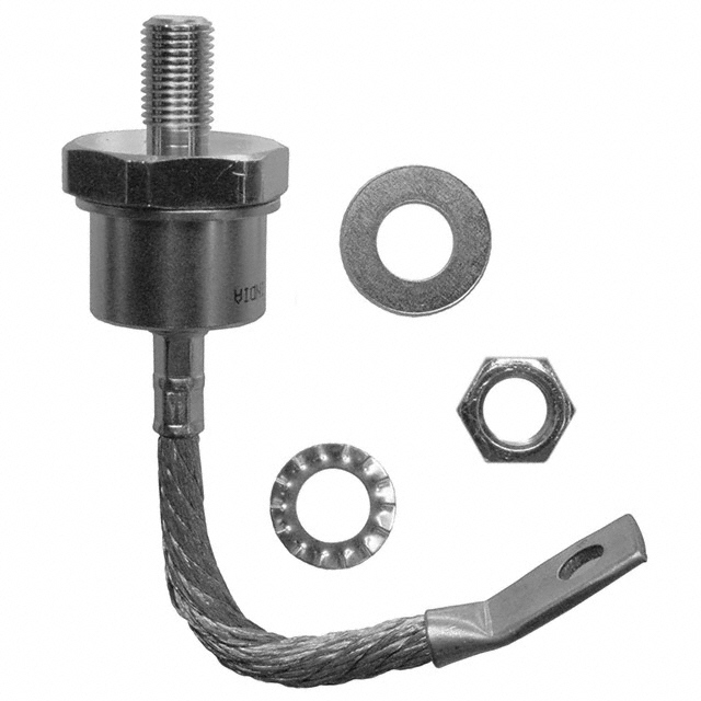
STANDARD RECOVERY DIODES Stud Version
Features
Alloy diode High current carrying capability High surge current capabilities Stud cathode and stud anode version RoHS Compliant
150A
Typical Applications
Battery charges Welders Machine tool controls High power drives Medium traction applications Freewheeling diodes
Major Ratings and Characteristics
Parameters
IF(AV) @ TC IF(RMS) IFSM @ 50Hz @ 60Hz I2t @ 50Hz @ 60Hz V RRM range TJ
45L /150K
150 150 235 3570 3740 64 58 100 to 600 - 40 to 200
Units
A °C A A A KA2s KA2s V °C
case style DO-205AA (DO-8)
www.irf.com
1
�45L(R), 150K/ KS(R) Series
Bulletin I2037 rev. C 10/06
ELECTRICAL SPECIFICATIONS Voltage Ratings
Type number Voltage Code
10 45L(R) 150K(R) 150KS(R) 20 30 40 60
VRRM , maximum repetitive peak reverse voltage V
100 200 300 400 600
VRSM , maximum nonrepetitive peak rev. voltage V
200 300 400 500 720
IRRM max.
@ TJ = 175°C
mA
35
Forward Conduction
Parameter
I F(AV) Max. average forward current @ Case temperature I F(RMS) Max. RMS forward current I FSM Max. peak, one-cycle forward, non-repetitive surge current
45L /150K
150 150 235 3570 3740 3000 3140
Units Conditions
A °C A DC @ 142°C case temperature t = 10ms t = 8.3ms A t = 10ms t = 8.3ms t = 10ms t = 8.3ms KA2s t = 10ms t = 8.3ms KA2√s No voltage reapplied 100% VRRM reapplied No voltage reapplied 100% VRRM reapplied Sinusoidal half wave, Initial TJ = TJ max. 180° conduction, half sine wave
It
2
Maximum I t for fusing
2
64 58 45 41
I 2√t
Maximum I2√t for fusing voltage
640 0.67
t = 0.1 to 10ms, no voltage reapplied (16.7% x π x IF(AV) < I < π x IF(AV)), TJ = TJ max.
V F(TO)1 Low level value of threshold V F(TO)2 High level value of threshold voltage r f1 r f2 V FM Low level value of forward slope resistance High level value of forward slope resistance Max. forward voltage drop
V 0.83 1.42 mΩ 0.91 1.33 V (I > x π x IF(AV)),TJ = TJ max. I = 471A, TJ = 25°C, t = 10ms sinusoidal wave
pk p
(I > x π x IF(AV)),TJ = TJ max. (16.7% x π x IF(AV) < I < π x IF(AV)), TJ = TJ max.
2
www.irf.com
�45L(R), 150K/ KS(R) Series
Bulletin I2037 rev. C 10/06
Thermal and Mechanical Specifications
Parameter
TJ Tstg RthJC RthCS T Max. junction operating temperature range Max. storage temperature range Max. thermal resistance, junction to case Max. thermal resistance, case to heatsink Mounting torque 45L Min. Max. Min. Max. 150K 150KS Min. Max. Min. Max. wt Approximate weight 45L Case style 150K-A 150KS
45L /150K
-40 to 200 -40 to 200 0.25 0.10 14.1 (125) 17.0 (150) 12.2 (108) 15.0 (132) 11.3 (100) 14.1 (125) 9.5 (85) 12.5 (110) 100 (3.5)
Units
°C
Conditions
K/W
DC operation Mounting surface, smooth, flat and greased Not lubricated threads
Nm (lbf-in)
Lubricated threads Not lubricated threads
Nm (lbf-in) g (oz)
Lubricated threads
DO-205AC (DO-30) DO-205AA (DO-8) B-42 See Outline Table
ΔRthJC Conduction
(The following table shows the increment of thermal resistence RthJC when devices operate at different conduction angles than DC)
Conduction angle
180° 120° 90° 60° 30°
Sinusoidal conduction Rectangular conduction Units
0.031 0.038 0.048 0.071 0.120 0.023 0.040 0.053 0.075 0.121 K/W
Conditions
TJ = TJ max.
Ordering Information Table
Device Code
45
1 1 2 3 4 45 = L = R = None =
L
2
R
3
60
4
Standard version Essential Part Number Stud Reverse Polarity (Anode to Stud) Stud Normal Polarity (Cathode to Stud)
Voltage code: Code x 10 = VRRM (See Voltage Ratings table)
www.irf.com
3
�45L(R), 150K/ KS(R) Series
Bulletin I2037 rev. C 10/06
Ordering Information Table
Device Code
15
1 1 2 3
0
2
K
3
R
4
60
5
A
6
- 15 = Essential Part Number - 0 = Standard Device - Case Style K = DO205AA (DO-8) KS = B-42 - R = Stud Reverse Polarity (Anode to Stud) None = Stud Normal Polarity (Cathode to Stud) - Voltage code: Code x 10 = VRRM (See Voltage Ratings table) - A = Essential Part Number for 150K (Omitted for 150KS) NOTE: For Metric Device M12 x 1.75 Contact Factory
4 5 6
Outline Table
45L Case Style DO-205AC (DO-30)
All dimensions in millimeters (inches)
4
www.irf.com
�45L(R), 150K/ KS(R) Series
Bulletin I2037 rev. C 10/06
Outline Table
150K Case Style DO-205AA (DO-8)
* FOR METRIC DEVICE: M12 X 1.75 CONTACT FACTORY
All dimensions in millimeters (inches)
2.03 (0.080)
21.47 (0.843) 21.20 (0.835) DIA. 4.34 (0.171) 4.09 (0.161) 10.2 (0.401) 9.2 (0.362)
27.17 (1.070)
150KS Case Style B-42
26.22 (1.032)
4.08 (0.161) 3.70 (0.146)
37.13 (1.462)
33.83 (1.332)
1.27 (0.050)
9.50 (0.374) 7.50 (0.295) 6.76 (0.266) 6.25 (0.246)
11.70 (0.460)
12.50 (0.492)
3/8"24UNF-2A
www.irf.com
18.00 (0.708)
14.00 (0.551)
5
�45L(R), 150K/ KS(R) Series
Bulletin I2037 rev. C 10/06
Maximum Allowable Case T emperature (°C) Maximum Allowable Case T emperature (°C) 200 190 180
Conduction Angle
200 190 180
45L...,150... S eries RthJC (DC) = 0.25 K/ W
45L..., 150... S eries R thJC (DC) = 0.25 K/ W
Conduction Period
170 160 30° 150 140 0 20 40 60 60° 90° 120° 180° 80 100 120 140 160
170 160 30° 150 140 0 50 100 60° 90° 120° 180° 150 DC 200 250
Average Forward Current (A)
Fig. 1 - Current Ratings Characteristics
Average Forward Current (A)
Fig. 2 - Current Ratings Characteristics
Maximum Average Forward Power Loss (W)
180 160 140 120 100 80 60
180° 120° 90° 60° 30° RMS Limit
K/ W .1 =0 A S R th K/ W 0.2 W K/ 0.3
4 0.
6 0. W K/
K/ W 0. 8
W K/
1
K/ W
elt -D
1.5 K/ W
aR
2K /W
Conduction Angle
3 K/
W
40 20 0 0
40 80
45L..., 150... S eries T = 200°C J
120
160 25
50
75
100
125
150
175
200
Average Forward Current (A)
Maximum Allowable Ambient T emperature (°C)
Fig. 3 - Forward Power Loss Characteristics
Maximum Average Forward Power Loss (W)
250
200
150
DC 180° 120° 90° 60° 30°
R th
2 0.
3 0. W K/
0. 6
4 0.
W K/
A S
K/ W
W K/
W K/ .1 =0 a e lt -D
K/ W 1K /W
1.5 K/ W
0. 8
R
100
RMS Limit
Conduc tion Period
2 K/
W
50
45L..., 150... S eries T = 200°C J
3 K/W
0
0 50 100 150 200
250 25
50
75
100
125
150
175
200
Average Forward Current (A)
Maximum Allowable Ambient T emperature (°C)
Fig. 4 - Forward Power Loss Characteristics
6
www.irf.com
�45L(R), 150K/ KS(R) Series
Bulletin I2037 rev. C 10/06
Peak Half S Wave F ine orward Current (A)
Peak Half S Wave Forward Current (A) ine
3500 3000 2500 2000 1500 1000
At Any Ra ted Load Condition And With Rated V RRM Applied Following S urge.
4000 3500 3000 2500 2000 1500 1000 500 0.01
Initial T = 200°C J @60 Hz 0.0083 s @50 Hz 0.0100 s
Maximum Non Repetitive S urge Current Versus Pulse T rain Dura tion. Initial T = 200°C J No Voltage Reapplied Rated VRRM Reapplied
45L..., 150... S eries 500 1 10 100
Numb er Of Equal Amplitude Half Cycle Current Pulses (N)
45L..., 150... S eries 0.1 Pulse T rain Duration (s) 1
Fig. 5 - Maximum Non-Repetitive Surge Current
10000 Ins tantaneous Forward Current (A)
Fig. 6 - Maximum Non-Repetitive Surge Current
1000
T = 25°C J 100 T = 200°C J 45L...,150... S eries 10 0 0.5 1 1.5 2 2.5 3 3.5 4 4.5 Instantaneous Forward Voltage (V)
Fig. 7 - Forward Voltage Drop Characteristics
T ransient T hermal Impedance ZthJC (K/W) 1 S teady S tate Value RthJC = 0.25 K7W (DC Operation)
0.1
45L..., 150... S eries
0.01 0.001
0.01
0.1 S quare Wave Pulse Duration (s)
1
10
Fig. 8 - Thermal Impedance ZthJC Characteristic
www.irf.com
7
�45L(R), 150K/ KS(R) Series
Bulletin I2037 rev. C 10/06
Data and specifications subject to change without notice. This product has been designed and qualified for Industrial Level. Qualification Standards can be found on IR's Web site.
IR WORLD HEADQUARTERS: 2 33 Kansas St., El Segundo, California 90245, USA Tel: (310) 252-7105 TAC Fax: (310) 252-7309 Visit us at www.irf.com for sales contact information. 10 /06
8
www.irf.com
�
很抱歉,暂时无法提供与“150KR60A”相匹配的价格&库存,您可以联系我们找货
免费人工找货