Bulletin I2771 rev. E 04/03
MT SERIES
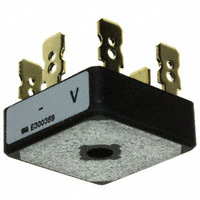
THREE PHASE BRIDGE Power Modules
Features
Universal, 3 way terminals: push-on, wrap around or solder High thermal conductivity package, electrically insulated case Center hole fixing Excellent power/volume ratio UL E 62320 approved Terminals Solderable as per MIL-STD-202 METHOD 208, solder: Sn/Pb (60/40); solder temperature: 235-260°C mx. time: 8-10 sec.
25 A 35 A
Description
A range of extremely compact, encapsulated three phase bridge rectifiers offering efficient and reliable operation. They are intended for use in general purpose and instrumentation applications.
Major Ratings and Characteristics
Parameters
IO @ TC IFSM @ 50Hz @ 60Hz I2t @ 50Hz @ 60Hz VRRM range TJ
26MT
25 70 360 375 635 580
36MT
35 60 475 500 1130 1030
Units
A °C A A A2s A2s V °C
100 to 1600 -55 to 150
www.irf.com
1
�26MT../36MT.. Series
Bulletin I2771 rev. E 04/03
ELECTRICAL SPECIFICATIONS Voltage Ratings
Voltage Type number Code
10 20 40 26MT../ 36MT.. 60 80 100 120 140 160
VRRM , maximum repetitive peak reverse voltage V
100 200 400 600 800 1000 1200 1400 1600
VRSM , maximum nonrepetitive peak rev. voltage V
150 275 500 725 900 1100 1300 1500 1700
IRRM max.
@ TJ max.
mA
2
Forward Conduction
Parameters
IO Maximum DC output current @ TC I FSM Maximum peak, one-cycle non-repetitive forward current Initial TJ = TJ max.
2
26MT
25 70 360 375 300 314
36MT Units Conditions
35 60 475 500 400 420 1130 1030 800 730 11300 0.86 1.03 6.3 5.0 1.19 V µA V mΩ
2
A °C A
120o Rect Conduction angle
t = 10ms t = 8.3ms t = 10ms t = 8.3ms
No voltage reapplied 100% VRRM reapplied No voltage reapplied 100% VRRM reapplied Initial TJ = TJ max.
It
Maximum I t for fusing Initial TJ = TJ max.
2
635 580 450 410
As
2
t = 10ms t = 8.3ms t = 10ms t = 8.3ms
2
I √t
2
Maximum I √t for fusing
2
6360 0.88 1.13 7.9 5.2 1.26
A √s I t for time tx = I2√t x √tx ; 0.1 π x IF(AV)), @ TJ max. TJ = 25 oC, I FM = 40Apk - Per single Junction TJ = 25 oC, per Junction at rated VRRM TJ = 25 oC, All terminal shorted f= 50Hz , t= 1s
VF(TO) 1 Low-level of threshold voltage VF(TO)2 rt1 rt2 VFM IRRM VINS High-level of threshold voltage Low-level forward slope resistance High-level forward slope resistance Maximum forward voltage drop Max. DC reverse current RMS isolation voltage
100 2700
2
www.irf.com
�26MT../36MT.. Series
Bulletin I2771 rev. E 04/03
Thermal and Mechanical Specifications
Parameters
TJ Tstg RthJC RthCS wt T Max. junction temperature range Max. storage temperature range Max. thermal resistance junction to case Max. thermal resistance, case to heatsink Approximate weight Mounting Torque ± 10% 1.42 0.2 20 2.0 1.35 0.2 K/W K/W g Nm Bridge to heatsink with screw M4
26MT
36MT Units
o o
Conditions
-55 to 150 -55 to 150
C C DC operation per bridge (Based on total power loss of bridge) Mounting surface, smooth, flat and greased
Ordering Information Table
Device Code
36
MT
160
1
2
3
26 = 36 = 25A (Avg) 35A (Avg)
1 2 3
-
Current rating code: Basic part number
Voltage code ( code x 10 = VRRM)
Outline Table
Suggested plugging force: 400 N max; axially applied to faston terminals
All dimensions in millimeters (inches) Not To Scale
www.irf.com
3
�26MT../36MT.. Series
Bulletin I2771 rev. E 04/03
Maximum Allowable Case Temperature (°C)
160
Instantaneous Forward Current (A)
1000
26MT.. Series 140
26MT.. Series
100 Per Junction
120 120 ° (Rect) 100
10 T J = 15O°C T J = 25 °C 1 0 0.5 1 1.5 2 2.5 3 3.5 4
80
60 0 5 10 15 20 25 30 Total Output Current (A)
Instantaneous Forward Voltage (V)
Fig. 1 - Current Ratings Characteristics
55 50 Maximum Total Power Loss (W) 45 40 35 30 25 20 15 10 5 0 0 5 10 15 20 0 25 25 50 120 ° (Rect) 26MT.. Series T J= 150 °C
2
1
A hS Rt
Fig. 2 - Forward Voltage Drop Characteristics
K/ W
/W
W K/
3K
= 7 0. W K/ -D aR elt
4K /W
5K /W
7 K/W
1 0 K /W
75
100
125
150
Total Output Current (A)
Maximum Allowable Ambient Temperature (°C)
Fig. 3 - Total Power Loss Characteristics
320 300 280 260 240 220 200 180 160 140 120 100 80 1 10 100
Number Of Equal Amplitude Half Cycle Current Pulses (N)
Peak Half Sine Wave Forward Current (A)
At Any Rated Load Condition And With Rated V RRM Applied Following Surge. Initial T J = 150 °C @ 60 Hz 0.0083 s @ 50 Hz 0.0100 s
Peak Half Sine Wave Forward Current (A)
400 360 320 280 240 200 160 120 80 0.01
Maximum Non Repetitive Surge Current Versus Pulse Train Duration. Initial TJ = 150 °C No Voltage Reapplied Rated RRM Reapplied V
26MT.. Series
26MT.. Series
0.1 Pulse Train Duration (s)
1
Fig. 4 - Maximum Non-Repetitive Surge Current
Fig. 5 - Maximum Non-Repetitive Surge Current
4
www.irf.com
�26MT../36MT.. Series
Bulletin I2771 rev. E 04/03
150 Maximum Allowable Case Temperature (°C) 36MT.. Series 130
1000 36MT.. Series Instantaneous Forward Current (A)
100 Per Junction
110
120 ° (Rect)
90
10 T J = 15O°C T J = 25°C 1 0 0.5 1 1.5 2 2.5 3 3.5 4
70
50 0 5 10 15 20 25 30 35 40 Total Output Current (A)
Instantaneous Forward Voltage (V)
Fig. 6 - Current Ratings Characteristics
80 70 Maximum Total Power Loss (W) 60 50 40 30 20 10 0 0 5 10 15 20 25 30 0 35 25 50 120 ° (Rect) 36MT.. Series TJ = 150 ° C
1
A hS Rt
Fig. 7 - Forward Voltage Drop Characteristics
= 7 0. W K/ -D a elt R
W
K/
2K
/W
3K /W
4K /W
5 K /W
7 K/W
10 K/ W
75
100
125
150
Total Output Current (A)
Maximum Allowable Ambient Temperature (° C)
Fig. 8 - Total Power Loss Characteristics
450 400 350 300 250 200 150 100 1 10 100
Number Of Equal Amplitude Half Cycle Current Pulses (N)
Peak Half Sine Wave Forward Current (A)
At Any Rated Load Condition And With Rated V RRM Applied Following Surge. Initial TJ = 150 °C @ 60 Hz 0.0083 s @ 50 Hz 0.0100 s
Peak Half Sine Wave Forward Current (A)
500 450 400 350 300 250 200 150 100 0.01
Maximum Non Repetitive Surge Current Versus Pulse Train Duration. Initial T J = 150° C No Voltage Reapplied Rated VRRM Reapplied
36MT.. Series
36MT.. Series
0.1 Pulse Train Duration (s)
1
Fig. 9 - Maximum Non-Repetitive Surge Current
Fig. 10 - Maximum Non-Repetitive Surge Current
www.irf.com
5
�26MT../36MT.. Series
Bulletin I2771 rev. E 04/03
Transient Thermal Impedance Z thJC (K/W)
10
Steady State Value: RthJC = 1.42 K/W (DC Operation)
1
0.1
0.01
26MT.. Series Per Bridge
0.001 0.001
0.01
0.1
1
10
100
Square Wave Pulse Duration (s) Fig. 11 - Thermal Impedance ZthJC Characteristics
Transient Thermal Impedance Z thJC (K/W)
10
Steady State Value: RthJC = 1.35 K/W (DC Operation)
1
0.1
0.01
36MT.. Series Per Bridge
0.001 0.001
0.01
0.1
1
10
100
Square Wave Pulse Duration (s) Fig. 12 - Thermal Impedance ZthJC Characteristics
Data and specifications subject to change without notice. This product has been designed and qualified for Industrial and Consumer Level. Qualification Standards can be found on IR's Web site.
IR WORLD HEADQUARTERS: 2 33 Kansas St., El Segundo, California 90245, USA Tel: (310) 252-7105 TAC Fax: (310) 252-7309 Visit us at www.irf.com for sales contact information. 04/03
6
www.irf.com
�
很抱歉,暂时无法提供与“36MT100”相匹配的价格&库存,您可以联系我们找货
免费人工找货